Friday, March 8, 2013

Reusing LEDs

Before I got a hold of the red LEDs I used in the 3x3 LED matrix, I was having a hard time finding a local source for LEDs of any kind. When the holidays rolled around I had a look at some of the Christmas tree lights that were for sale and for a few dollars I bought a string of 100 white lights that look like this:


As you can see from the picture, the head is concave. This type is easy to see from a distance but doesn't look very good on a breadboard. The string of lights this LED came from consists of four seperate strands. The first few LEDs on each strand have resistors soldered to their legs as you can see here. This makes them convenient to plug into a breadboard, even though concave LEDs don't look very good up close.

Later on I found a similar string with frosted convex LEDs. Each of the four strands of 25 LEDs was a different color. I bought several boxes and in the end I paid less than 3 cents per LED! The first few lights on each strand also have resistors soldered to the legs:


One thing I found very interesting about these LEDs is that they grow very brightly. The resistors soldered to the legs are Orange-Black-Red-Gold. This should mean that they are 3000 ohm resistors. In order to get 20mA out of these LEDs I would need around 60 volts. However, when hooked to the 3.6v of my LaunchPad they glow very brightly. By my calculations, if the forward voltage of the LEDs is around 2 volts, the LEDs should be using less than 1mA when the supply voltage is 3.6v. Clearly something isn't as it seems!

Hopefully, I can repurpose some of these LEDs to make a matrix. This should be convenient since they already have wires soldered to their leads. Since each string has four different colors, I don't have enough LEDs to make a large matrix of only one color. My plan now is to combine a red, a green, and a blue LED together to make one RGB pixel. Like other matrixes I saw on the internet, I tried ping pong balls as diffusers. Here is the result using four of the colored LEDs and one of the white ones:


They seem to diffuse very well but ping pong balls here are too expensive to be used for a whole matrix. Once I find a better way of diffusing light, I can move on to soldering the matrix.

Wednesday, March 6, 2013

3x3 LED Matrix

A friend of mine recently asked about making a small LED sign for his business that can scroll text. It seems that buying such signs is pretty expensive. To give him a little demonstration of how it would work I made a small 3x3 matrix of LEDs using a 74HC595 shift register. Using multiplexing it is possible to run a 4x4 matrix with only one shift register but I didn't have that many matching loose LEDs on hand. I was able to draw some simple patterns using an MSP430 and even do some PWM to dim the LEDs.


One thing that surprised me was that the cheap red LEDs I used burned out almost instantly when hooked up to the supply rail without a resistor. Running an LED without any kind of current limiting is of course a bad idea but it was a surprise that these failed so quickly. Others I have experimented with worked without any noticeable damage for a few seconds when hooked up to the few 100mA that the MSP430 LaunchPad can source.

Also, although these LEDs appear to be identical and were bought at the same time from the same store, one of them seems to glow at least twice as bright as the others. Some LEDs I have used seem to glow a little dimmer than others from the same batch but I've never seen one like this that glows so much brighter. I'm not sure what causes this.

Tuesday, March 5, 2013

MSP430 and C115 LCD

Recently I visited a local cell phone repair shop in search of LCDs with pads large enough to solder. What I came out with was a color display from a Motorolla E370 and a two-inch Motorolla C115 monochrome display. There don't seem to be any datasheets or code examples for the E370 on the internet but I was able to get the C115 running with an MSP430.


The first thing I did was solder wires to the ribbon cable. The pads were wide enough to attach normal breadboard wires to. Soldering them individually turned out to be pretty difficult so I first covered all of the pads in solder then placed the wires on the pads and melted the solder by putting the soldering iron on top of the wires.

To run the display I looked at some AVR code I found on a Russian site and tried to adapt it. The LCD uses the I2C protocol so I looked up how to use the UART module in the MSP430G2553 I was using. The AVR code sends the address of the LCD as a 7-bit address shifted left one bit. When I used this address with the MSP430 the LCD didn't respond and I started to suspect that it was broken. Then I decided to use some code I found from TI that checks to see if there are any devices connected at a particular address and used that to scan all the possible I2C addresses. The LCD responded at an address I wasn't expecting. It turns out that the address was wrong because the UART of the MSP430 expects an unshifted address, whereas the AVR code was sending an address that had already been shifted.

After I had the display running, I wrote a few lines of Visual Basic code to convert a bitmap into a C array. Here is a picture I made to test the display:


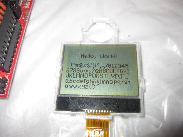
Then I worked on a font for the display. There are a lot of 5x7 fonts and not much room for creativity at such a small size but I went ahead and made my own character set anyway. My goal was to make the characters slim so that I could fit as many as possible on one line. As you can see in the picture, the font is variable width since any unused spaces aren't drawn. I also made sure that characters like g and j are drawn one pixel lower.


This LCD wasn't too hard to get running and hopefully I can use it in a future project.