Recently I visited a local cell phone repair shop in search of LCDs with pads large enough to solder. What I came out with was a color display from a Motorolla E370 and a two-inch Motorolla C115 monochrome display. There don't seem to be any datasheets or code examples for the E370 on the internet but I was able to get the C115 running with an MSP430.

The first thing I did was solder wires to the ribbon cable. The pads were wide enough to attach normal breadboard wires to. Soldering them individually turned out to be pretty difficult so I first covered all of the pads in solder then placed the wires on the pads and melted the solder by putting the soldering iron on top of the wires.
To run the display I looked at some AVR code I found on a Russian site and tried to adapt it. The LCD uses the I2C protocol so I looked up how to use the UART module in the MSP430G2553 I was using. The AVR code sends the address of the LCD as a 7-bit address shifted left one bit. When I used this address with the MSP430 the LCD didn't respond and I started to suspect that it was broken. Then I decided to use some code I found from TI that checks to see if there are any devices connected at a particular address and used that to scan all the possible I2C addresses. The LCD responded at an address I wasn't expecting. It turns out that the address was wrong because the UART of the MSP430 expects an unshifted address, whereas the AVR code was sending an address that had already been shifted.
After I had the display running, I wrote a few lines of Visual Basic code to convert a bitmap into a C array. Here is a picture I made to test the display:
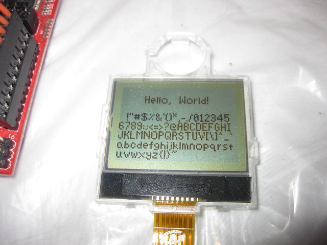
Then I worked on a font for the display. There are a lot of 5x7 fonts and not much room for creativity at such a small size but I went ahead and made my own character set anyway. My goal was to make the characters slim so that I could fit as many as possible on one line. As you can see in the picture, the font is variable width since any unused spaces aren't drawn. I also made sure that characters like g and j are drawn one pixel lower.
This LCD wasn't too hard to get running and hopefully I can use it in a future project.


hello, great !!
ReplyDeleteI tested the display with energy and ccs and have failed to work ...
You could help me?
I appreciate the help
oiramzenitram@yahoo.es
hola como estas podrias ayudarme tengo un pantalla similar pero no se como e la denominacion de cada uno de los pines que sale de la pantalla
ReplyDeleteThe display driver is a ST7558. Try googling "Arduino C115" to find a page with the pinout. For example: https://github.com/kr4fty/ST7558-Motorola-C115-LCD-Library
ReplyDelete