Friday, November 29, 2013

RPN Scientific Calculator: Update

As I mentioned in the last post about this project, I added a second MSP430 because the firmware was getting too large. In the end hardware UART turned out to be a good choice for communication between them. It works very fast and is reliable. The first MSP430 is responsible for reading the keyboard, controlling the LCD, handling the interface, and performing checks such as division by zero before passing on the addresses of the values  to be calculated to the second MSP430. The firmware for the first chip comes to a little over 13KB. The second MSP430 does all the actual calculating since it is connected to the SRAM. Its firmware is about 10KB.

The software part of this project is almost finished. One thing I added was a settings page. The accuracy of calculations can be set anywhere between 6 and 32 decimal places. There are also options to use scientific notation and switch between degrees and radians for trig functions. The only things left to add are a battery meter and support for two stacks. A second stack is not really necessary but as it is now, only one half of the 128KB SRAM is usable since the 17th address pin is not hooked up. I plan to add a button so that the second half of memory can be used as a separate stack.

Although I planned on adding programming features at the beginning, I may not have time. The 43oh forum is having a project of the month competition I would like to enter this project in and I will need to hurry to finish putting together the hardware and making a case for it. If there is time left at the end of the month I may add a simple key stroke programming mode. It is a little disappointing that I did not get to this but on the other hand, it is convenient to have a firm end to this project. It would be easy to keep adding features but even now I feel like I have stretched the project beyond what the hardware can reasonably handle. I have plans for other calculators that will be programmable but they will use a more powerful chip than the MSP430G2553 and they won't use SRAM controlled by shift registers.

One change I made to the hardware was to use a different LCD. The new LCD is also 20x4 but it was much cheaper. The old LCD was quite expensive and I would like to keep using it rather than commit it to this project. The new LCD is 10cm wide instead of 8cm like the old one so I decided to turn the keypad long ways to save room. Here is the layout I plan to use:


Wednesday, October 30, 2013

Microcontroller Showdown, Part 2

Here are the results for the tests I did with the MSP430 and the LPC1114. Lately I have been busy with work so I haven't had a chance to do anything with the other three chips. I do have tool chains set up for them and I plan to run the same tests on them soon too.

To time the tests I used an MSP430 LaunchPad which waited for a pulse from the tested chips to begin and end timing. The timer was run from the VLO which is accurate to ±3% so the results are not exact but they give a rough idea of the difference in speed. The tests were done inside two nested loops which iterate altogether 2,400,000 times. Each operation is done once per iteration except adding and GPIO operations which are done 10 times since they should be much faster. At first I did each test 5 times and took the average but then I did them only once since the results were usually very close and some of the later tests took quite a while. To begin with I timed how long the empty loop took then I subtracted that time from the results to get the actual time the operations took. For both chips I used gcc to compile with both -Os and -O3, although there wasn't really a difference except for the BCD routine tests.

As you can see from the table, the LPC1114 was much faster than the MSP430, even running from the bottlenecked flash. The results would be even faster if the tests had been copied to RAM and run from there. I was also surprised to realize that the LPC1114 has a barrel shifter which is very handy. Another neat feature is GPIO masking. Each mask is memory mapped so individuals pins can be toggled with a single write to memory. This allows GPIO operations to be much faster than the traditional load, modify, and store routine.

Monday, September 30, 2013

Microcontroller Showdown, Part 1

Recently I bought some LPC1114 microcontrollers from NXP. They come in DIP packages and feature an ARM Core M0. Although comparing the clock speeds of different architectures is not the best indicator of speed, I would still expect this chip running at 50MHz to be faster than the MSP430s running at 16MHz that I have been using until now. Later I found out that the flash of the LPC1114 only runs at 20MHz, which will bottleneck any programs running from there. Running from RAM would be much faster but the chip only has 4KB of SRAM. On the other hand, it does have a three-stage pipeline. Value-line MSP430s only have instruction-prefetch. All of this makes it a bit difficult to know how much faster one chip would be than another, so I have decided to run a few benchmarks.

Another architecture I have been interested in lately is the 8051. This is much older than the other two architectures I want to check but it remains popular with some people. Instructions take 12, 24, or 48 cycles to execute, which is less efficient compared to an MSP430 which needs only 3-6. Some modern 8051s feature a full-pipeline and clock speeds over 30MHz. These are interesting to me because I think they may be able to outperform the MSP430 in some ways. I was able to sample some AT89LP6440s from Atmel and a DS89C450 from Maxim Integrated which both come in DIP packages. The AT89LP6440 can fetch one byte per clock cycle from memory, meaning that it should in practice run slower than 1 MIPS per MHz but still much faster than other 8051s. It does have a hardware multiplier which surprised me to find out. The datasheet for the DS89C450 lists it as one clock-per-machine cycle, so it should run faster MHz per MHz than the AT89LP6440. It can also run at 33MHz compared to the AT89LP6440 at 20MHz.

The last microcontroller I will test is the Z16F from Zilog. This is a 16-bit CISC design descended from the 8-bit Z80. According to the Zilog website, it outperforms many RISC designs in the same class. It can do 32-bit ALU operations, has a hardware multiplier, and does some pipelining. I know the least about this chip but the design is interesting and I may use it in a future project if it performs well.

Here are some specifications of the microcontrollers that will be involved:

Microcontroller   Clock Speed   RAM   Flash   Core
MSP430G255316MHz0.5KB16KBMSP430
LPC1114FN2850MHz4KB32KBARM Core M0
AT89LP644020MHz4KB64KB8051
DS89C45033MHz1KB64KB8051
Z16F281020MHz4KB128KBZNEO

There are many factors that need to be taken into account when choosing a microcontroller. For this test I have decided to test only calculation speed and to ignore other factors such as the peripherals. Consequently, the results will not be relevant to some people. This also will not tell me which microcontroller is the best overall. These particular chips are dissimilar in many ways and this is not a comparison of microcontrollers from the same class. They are only being compared because I am curious about them.

One good reason to do this test is so that I have an excuse to set up the tool chains and programmers for all of these chips. This will take some time so I will release the results in a few parts. It will give me a break from the RPN Scientific Calculator I am making.

Sunday, September 8, 2013

RPN Scientific Calculator: Second MSP430

The next step for the calculator is the interface. The code for handling input ended up being fairly long but now entering numbers works as well as the basic math functions. A lot of flash space was taken up by the mathematical checks that must be done with trig functions to convert them to useable forms and ensure that they are within a valid range.
 
At this point the firmware took up about 14KB, which is close to the 16KB I have to work with. There probably isn't enough space left to add all of the functions and accompanying checks so I decided to add another MSP430. This will give me more more space but also make things more difficult since I will have to coordinate communication between the two. Moving to another chip with more Flash would be an option but I have plenty of MSP430s on hand and I don't want to move chips now that I have everything working well together.

Since I only have one LaunchPad I had to program the second MSP430 on a breadboard. This is pretty easy to do. The LaunchPad has jumpers on the RST and TEST lines where the programming signals can be diverted and used elsewhere. In this case they go to the breadboard, and a dip switch is used to select whether the programming signals go back to the LaunchPad or to the breadboarded chip.

With two chips I have a lot of left over pins. This let me eliminate the read and write shift registers used with the SRAM. The data port is now connected to one whole port of the second MSP430 instead and should work a little faster. The next step was to establish communication between the two chips. Using one pin for data and another as a clock signal, I was able to do some simple data transfers. Unfortunately this caused an error, usually after several thousand successful transfers. It's not clear whether the error was caused by hardware problems like breadboard crosstalk or if there was a timing error of some kind in my code. My plan now is to use hardware UART between the chips instead. Hopefully this will be more reliable.

There are now also enough pins to drive the LCD directly instead of using a shift register. When I tried doing this before with a 16x2 LCD it worked well but at some point in the project it began to randomly stop working. In retrospect I think it may have started after adding some of the other components to the project. In any case, sending signals to the 20x4 LCD from the LaunchPad does not work at all. This problem will have to wait until I can replace my broken multimeter and test all the voltages involved.

Saturday, August 17, 2013

RPN Scientific Calculator: Tweaks

Recently I was able to get some new components and took the chance to make a few tweaks to the calculator. First of all, I hooked up a new 20x4 character LCD to replace the 16x2 version I was using before. It is gray with black letters and I like how it looks. With this I will be able to make the bottom row of the screen a menu like the kind some of the later HP calculators use. The LCD itself came with male headers so it can be plugged into a breadboard, but there was no convenient place to put it so I decided to run wires from the headers to the breadboard instead. The LCD worked fine at first but quickly became corrupted after I wound the wires into a loop to make them neater. This was causing crosstalk and the problem disappeared when I separated the wires.

I also added a CMOS 555 timer to generate the negative voltage for the LCD. This frees up a microcontroller pin that I am now using to independently drive the input shift register of the RAM. Now I can read the external RAM and the keyboard at the same time without worrying about coordinating interrupts. In order to save energy I decided to use the smallest capacitor and the largest value resistors I could for the timer. Unfortunately, none of the resistor values I had on hand would give me the 30 Hz or so the microcontroller was generating. 48 Hz was the closest I could get using a 0.1 uF capacitor and 100k ohm resistors for R1 and R2. Adding a 470 ohm resistor to the output of the 555 gave a good contrast and should also keep the contrast constant if I try to run everything from a battery later.

The last thing I did was to expand the CORDIC tables to 32 bits wide instead of 16. Using a 16 bit wide table gives around 14 decimal places of accuracy which is sufficient for calculating logarithms. A problem arises, however, when that logarithm is used to calculate things like exponents because those 14 places of accuracy also include the whole part of the answer. A simple calculation like 8^9 only offers 5 decimal places of accuracy after the decimal since the whole part is 9 digits long. The new version takes about 6 seconds to calculate "atan(tan(37))" This is very slow so I will let the user set the precision in settings.

Monday, July 29, 2013

RPN Scientific Calculator: More CORDIC Routines

After finishing the CORDIC routine for logarithms I started on the CORDIC routine for trig functions. For this I needed a different look up table and a different function, but it didn't take up much room in the flash. The table for pre-computed logarithms is stored compactly in flash and the same routine that unpacks it into the external memory is also used to unpack the trig table. With this I can calculate sine, cosine, tangent, and arctangent. It should also be possible to calculate arcsine as well but I haven't tried yet.

To test these new function I tried calculating atan(tan(37)). When using 16 decimal places for the calculations this gives the answer 36.9999999999999781, which is pretty accurate. Unfortunately, this took over two seconds, which is just too slow. The logarithm and powers of e functions were at least twice as fast. In order to speed things up I tried to eliminate as many reads and writes to the external memory as I could. One thing I didn't notice when I wrote the original functions is that the loop condition for a for loop is recalculated each iteration. When the condition depends on a variable in external memory, the variable is fetched on every iteration, which is wasteful if the variable hasn't changed. After changing the code to use local copies of external variables whenever possible, I was able to cut down external memory access by almost 25%.

25% wasn't quite enough so I looked at the code I was using to right shift. This allows me to divide numbers by 2 quickly but takes some extra coding since shifting in BCD is a little more complicated than a normal binary shift. Because of the extra work involved in keeping everything straight during BCD shifting, I was doing shifts one bit at a time. This means a 58 bit shift, for example, would simply do 58 shifts of 1 bit each. As you can imagine this is not efficient and was a big part of the slow down in the code. My solution was to use as many 4-bit shifts as needed, then a few 1 bit shifts at the end to finish it off.

Shifting by 4 bits in BCD is fairly easy. As you probably know, shifting by 4 bits is the same as dividing by 16, and dividing by a number (16 in this case) is the same as summing the results of dividing each decimal place by that number. Since there are only 10 possibilities (0-9) for each decimal place, I stored the results of dividing each possibility by 16 in a look up table and used that to sum the results. Here is an example:

789 ÷ 16 = 700/16 =   4375
                  80/16 =     5000
             +     9/16 =      5625
                               49.3125

The values 4375, 5000, 5625, etc are stored in the look up table. The sum of these results are stored in local RAM since 6 bytes is enough to keep track of the summing long enough to deal with any carries before finally writing the last byte to the external RAM. Doing it like this I only need to read and write every decimal place once per 4-bit shift. This cuts down the number of external memory accesses down to almost one third of what it was at the beginning and allowed me to calculate atan(tan(37)) in a little over a second. All of this fits in 8.1K of Flash meaning I just broke the halfway mark of what the MSP430G2553 chip I am using can hold. If there is any space left over at the end, I would like to implement a similar 8-bit shift routine as well to speed things up even more.

Wednesday, July 10, 2013

RPN Scientific Calculator: Division and Logarithms

After rewriting the multiplication function I started on the division routine. There are several ways to do this. I used the subtract and shift method. It takes up a little more than 150 lines of code which makes it about twice as big as the multiplication routine. Unlike with the other operations, with division a maximum number of decimal places has to be specified. It seems unlikely that I would ever need more than 16 places, which makes me think a fixed place format might have worked too. This is still possible if I need to shrink the program size.

The next step is to implement logarithms and powers of e. This will be useful on its own but will also let me calculate powers and roots. One way I found to calculate logarithms is with a Taylor series like this: 

ln[(1+x)/(1-x)]=2(x+x3/3+x5/5+x7/7+....)

This seems ideal since it only requires one loop and several multiply and divide operations which shouldn't take up much room in Flash. Even with the the MSP430 running at 16MHz, it rook over 3 seconds to calculate ln(7). In an effort to speed things up I examined the code for multiplying and dividing but didn't find much to improve. One thing I did change was the addition routine. I was adding a 0 to the beginning of every result so that there would be room for a 1 if I needed to carry. However, in most cases the 0 wasn't needed and when doing repeated additions during multiplication, the 0s accumulated at the beginning of the result wasting memory. Removing these 0s wasted time so I changed the addition code to only add the 0 when necessary. This still didn't make it much faster, though.

Next, I ran the code on my PC and noticed that it needed to access the external memory over 2 million times to calculate the logarithm to 16 decimal places. Clearly this was the bottleneck. The next idea I tried was the CORDIC method which is ideal for small microcontrollers like the MSP430. This uses a precomputed table and only needs adds and bit shifts, two things that microcontrollers can do much more efficiently than multiplying and dividing. Using this method I can calculate e^x and ln(x) for a wide range of values in less than one second because it only needs about 50,000 accesses to the external memory.

After I finished the ln function but before I started on the e^x function, I noticed that the program was already 6.5k. This is a little concerning since 16k is the max size for the program and there are still many more features to add. One thing that can reduce size is the static keyword. Making all my functions static shrunk the program size down to only 3.7k. After adding some more entries to the CORDIC table, improving the ln function, and adding the e^x function, the program size was back up to almost 6.5k again. This seems very strange since the program is now almost 1,000 lines and the ln functions only takes 50 lines. In fact commenting out the ln function reduces the program down to only 4.4k. Why this one small function should suddenly add more than 2k to my code is not clear but I hope to figure it out soon.

Wednesday, June 12, 2013

RPN Scientific Calculator: Software Update

Work continues on my calculator. Each byte of a BCD number now holds only one digit instead of two. This eliminates the functions that were needed to align and pad numbers when every byte held two numbers. It also makes calculations a little simpler and reduces the amount of space the functions take up in the Flash.

Another improvement is that arrays can be stored in the external SRAM and accessed similarly to how internal memory is accessed. To read or write anything to the external memory a function has to be used. That means a simple equation like this:
X+=Y*Z-Q;
would become this if those variables were stored externally:
 RAM_Write(X,RAM_Read(X)+(RAM_Read(Y)*RAM_Read(Z)-RAM_Read(Q));
This is difficult to decipher and inconvenient to use when writing code. My solution was to make a small program that preprocesses the source code and replaces any variables that should be stored externally with their corresponding read and write commands. These variables are marked off with #pragma directives. #pragma is a note to the compiler to do something special that may be specific to that compiler. If the compiler doesn't recognize the directive, it is ignored. Here is an example of what the preprocessor would do.

This is unprocessed code:
void puts(unsigned char *msg)
{
     #pragma MM_VAR msg
     for (int i=0;msg[i];i++) putchar(msg[i]);
}

int
main()
   
     #pragma MM_OFFSET 200
     #pragma MM_DECLARE

     unsigned char text1[30];
     unsigned char text2[30];
     #pragma MM_END

     text1[0]='A';
     text1[1]=0;
     puts(text1);
}
 This is preprocessed code:
void puts(unsigned char *msg)
{
     #pragma MM_VAR msg
     for (int i=0;
RAM_Read(msg+i);i++) putchar(RAM_Read(msg+i));

}

int
main()
   
     #pragma MM_OFFSET 200
     #pragma MM_DECLARE

     unsigned char *text1=(unsigned char*)200;
     unsigned char *text2=(unsigned char*)230;

     #pragma MM_END

     RAM_Write(text1+0,'A');
     RAM_Write(text1+1,0);

     puts(text1);

}
Arrays are converted to pointers that store offsets to the external memory. This way none of the function prototypes have to be changed. The code should work the same way whether the variables are stored in internal or external RAM. External memory can be turned off if needed to make tracking down bugs easier. One disadvantage to this is that function arguments must be either internally or externally stored but a function can't accept both types for one argument. For things that need both I will need a wrapper function. The preprocessor doesn't support all of the C standard since I only spent about a day on it. Adding support for all of the possible ways there are to access a variable would take a lot more work and I wouldn't be likely to use that functionality anyway. Things like variable names that span multiple lines or variable assignments inside of other statements aren't supported but I didn't end up using any of those features in my code.

The new code for adding and subtracting BCD numbers fits in about 2K, including LCD driving code. Using the preprocessor to store all the values externally adds another 500 bytes. The code for multiplication is also much smaller than the last version.

Friday, May 31, 2013

RPN Scientific Calculator: External RAM

The last part of the hardware needed to complete the calculator is external RAM. Even if it does not have any programming capabilities, it will still need more RAM for the stack than the 512 bytes an MSP430G2553 has. Microchip makes 128K SRAM chips that are small and accessible over SPI that would work well for this project. However, I had this parallel SRAM chip from Alliance left over with nothing in mind for it and I decided to use it instead. It needs 8 pins for data so I am using one 74HC595 for output and one 74HC165 for input. The 17 address pins are driven by two more 74HC595s. This only gives 16 outputs so the 17th address pin is tied directly to a microcontroller pin. This will allow me to have two banks of memory, although I don't have any use for that at the moment. Putting this together took a lot of wiring but it wasn't too difficult.

Accessing large amounts of memory like this over serial can be a speed bottleneck, so I decided to use the USCI module of the MSP430 to do hardware SPI and speed up transfers. After learning how it works I saw that it is really easy to set up and convenient to use. As with the shift registers that read the button matrix, I decided to share the clock but to use different latches. The USCI has separate data in and data out pins so those aren't shared. This is handy for reading the 165 shift register because after it is latched you can just push a dummy value out then read the USCI receive buffer. There is a flag to control whether the USCI stores data in MSB (Most Signicant Bit) or LSB format but it can't be set separately for the input and output buffers. This means data goes out with the right orientation but comes in backwards. To remedy this I hooked up the data inputs of the 165 in reverse order to the data bus of the SRAM.

To test the speed of this setup I made a test program to write a pattern to every byte of the RAM then read it back and make sure the values are as expected. This worked fine at 1MHz but the LCD glitched when I tried running at 16MHz. After I fixed that I was able to finish the whole test in about two seconds. That is pretty good throughput for a calculator!

Now that the RAM is working, the hardware part is finished. It is good that I don't have anything else to add since all of the microcontroller pins are taken up. In fact the input shift registers for the SRAM and keypad share the same latch since it is unlikely that they will ever be used at the same time. If I need anything else I will have to use the two remaining bits in the keypad shift register (the keypad only has 6 rows and the LCD only needs 5 bits) or add another shift register. Now I can focus on the programming and worry about hardware again when it is time to make a circuit board. Here is what the hardware looks like now:


Thursday, May 30, 2013

RPN Scientific Calculator: Keypad

The next step of the hardware for my calculator is a keypad. I finished this several weeks ago but I haven't posted anything about it because I didn't have any pictures until now.


As you can see, the construction is pretty simple. My local shop had a new kind of perfboard that I wanted to try. It seems to be a little stronger than the kind I used before but still not really stiff like some of the high quality ones I have seen. It took some time to solder this together but it worked well in the end. Only one button connection had to be resoldered.

The circuit is a standard button matrix. A signal is sent through each of the green lines in turn and if any of the buttons are held down the signal will travel out of one of the yellow output lines and be recorded. Each button has a diode to ensure that the signal can only go one way. As you can see from the back side of the board, the columns are connected by solder and the rows by yellow jumpers. After I had soldered most of the columns, I realized that the two legs on each side of this kind of button are connected internally and don't have to be soldered together. The next time I make a button matrix I will leave them unsoldered so I will have room to make the rows out of solder as well. Avoiding jumper wires like I used here will make soldering simpler.

To read the matrix I am using a 74HC165 and a 74HC595 shift register. Output shift registers can easily be chained together but I also found out that an output and input shift register can be chained together as well sharing the same data, clock, and latch lines. Here I decided to use separate latches since the 165 is reading the output of the 595 but they do share data and clock lines which uses less microcontroller pins

Most of the time the shift registers will go unused since scanning the matrix only takes a fraction of a second. To save even more pins I decided to drive the LCD using the 595 shift register as well. This works out as long as communicating with the LCD and reading buttons never overlaps. I will have to take this into consideration if I decide to use an interrupt to read buttons. This also fixed a strange and unsolved issue that would occasionally cause the LCD not to receive commands when it was being driven directly by microcontroller pins.

Saturday, May 18, 2013

RPN Scientific Calculator: Multiplication

The next step of the software for my calculator is multiplication. In Binary Coded Decimal (BCD) this is fairly straightforward. Every decimal place of the first number has to be multiplied by every decimal place of the second number. The tricky part is keeping the results lined up and then putting the decimal point in the right place at the end. Here is an example running on the MSP430:


One advantage of BCD is that it avoids the rounding errors that occur in floating point calculations. This quickly becomes apparent when you start multiplying decimal numbers. Even in this example using fairly small numbers there is a rounding error:
Floating Point:
835.2533 x 907.042 = 757609.823739

Binary Coded Decimal
835.2533 x 907.042 = 757609.8237386
For most uses floating point offers enough precision but a scientific calculator should be as accurate as possible, so BCD is a better choice.

While working on this I was able to find a bug in my code for addition and fix it. I also added a function to shift numbers one decimal place so they will be aligned properly for multiplication. This routine is sometimes necessary since each byte holds two decimal numbers. Routines like this take up space in Flash, which is limited to 16K on value-line MSP430s. One way to avoid having to shift numbers is to let each byte represent one number instead of two. Although this would use twice as much RAM, it would simplify programming and use less space in Flash. This is what I will do if I run out of room for the firmware. Right now I plan to use 128K parallel SRAM chips from Alliance, so running out of RAM wouldn't be a problem. (Of course 8k of SRAM would have been enough but I don't have any of those with me.) Another option would be to write all or part of the BCD routines in assembly. This would help a lot since the MSP430 has an op-code to add BCD numbers. It also handles carries natively which is more efficient than storing it in a variable and checking it explicitly like my code does now. Currently, the program is only 3.3K including the part that handles the LCD. How much I can fit in the remaining Flash will determine what changes I make.

Monday, April 8, 2013

New Project: RPN Scientific Calculator

My interest in electronics started because I would like to build calculators like the ones I used to collect. Now I plan to build a scientific RPN calculator. A three inch graphical LCD would work well for this but most cell phone screens I can easily find are a little bit too small. For the time being I will continue using the 16x2 LCD I found.

For this project I intend to use an MSP430. The challenge of this will be that the MSP430G2553s I have only have 512 bytes of RAM. To begin with I decided to start on the programming since this will probably be much more work than the hardware. Although I want this calculator to use RPN, it would also be good if it could evaluate algebraically as well like the HP-49G. It will hopefully also be useful to have a small parser that works on a microcontroller for some other projects I want to do. Here is the parser running on my LaunchPad and evaluating the equation 13*(4+25*13)/((67-33)*2^3):


At first I wanted to use recursion because this can really simplify parsing but that's not really an option since it would use a lot of stack space. Instead, it evaluates any expressions it can and stores the result in memory then writes a pointer to that memory in the place where the expression was. Doing it like this instead of tokenizing the whole string before evaluating saves memory. The results of operations are stored starting at the end of the string that holds the expression so that as the expression is evaluated and becomes smaller, memory is freed which can be used to store more results. So far this parser fits in about 2k of Flash.

The second part I worked on is a Binary Coded Decimal format. This will be more accurate than floating point since it will be able to store any number that will fit in available memory. Each byte of data contains two numbers from 0 to 9. Now numbers are limited to 512 digits in length but this can easily be increased, although it probably wouldn't be useful on such a small screen. I have code for adding and subtracting, so multiplication and division should be easy to implement using these. I was able to fit this into less than 2k of  Flash so with the parser I should still have about 12k of flash for other functions. Here is an example using numbers small enough to fit on the screen:


Saturday, April 6, 2013

16x2 LCD and MSP430

Recently, I found a local electronics shop that carries 16x2 LCDs that are HD44780 compatible. This type of LCD is really common and it wasn't too hard to get it working with an MSP430.


The hard part was that the LCD expects 5 volts, although the LaunchPad supplies only 3.6 volts. I did some reading and it turns out that the logic part of the LCD can run on as little as 2.7 volts. The contrast, on the other hand, expects 5 volts. Even with the pin that controls contrast connected to ground, nothing can be seen on the LCD. One solution is to feed this pin some negative voltage.

Negative voltage can be generated with a charge pump made of only two capacitors and two diodes. In the picture above you can see them behind the LCD. They need a pulse to work which I generated with my MSP430. This worked well but I began to think that it might be a bad idea to charge capacitors through a microcontroller pin. My first try was to switch the voltage with a transistor. This didn't work because I could only source current. Then I found out about push-pull stages. This is a handy way to sink and source current with only two transistors.

My next plan was to create the pulses for the charge pump externally so the MSP430 wouldn't have to worry about doing it. The 555 timer I bought for the job turned out to be 5 volts also so that didn't help. I tried modifying a circuit I found to flash LEDs using capacitors and transistors but it wasn't very reliable. For now I will stick with doing it with the MSP430.

Friday, March 8, 2013

Reusing LEDs

Before I got a hold of the red LEDs I used in the 3x3 LED matrix, I was having a hard time finding a local source for LEDs of any kind. When the holidays rolled around I had a look at some of the Christmas tree lights that were for sale and for a few dollars I bought a string of 100 white lights that look like this:


As you can see from the picture, the head is concave. This type is easy to see from a distance but doesn't look very good on a breadboard. The string of lights this LED came from consists of four seperate strands. The first few LEDs on each strand have resistors soldered to their legs as you can see here. This makes them convenient to plug into a breadboard, even though concave LEDs don't look very good up close.

Later on I found a similar string with frosted convex LEDs. Each of the four strands of 25 LEDs was a different color. I bought several boxes and in the end I paid less than 3 cents per LED! The first few lights on each strand also have resistors soldered to the legs:


One thing I found very interesting about these LEDs is that they grow very brightly. The resistors soldered to the legs are Orange-Black-Red-Gold. This should mean that they are 3000 ohm resistors. In order to get 20mA out of these LEDs I would need around 60 volts. However, when hooked to the 3.6v of my LaunchPad they glow very brightly. By my calculations, if the forward voltage of the LEDs is around 2 volts, the LEDs should be using less than 1mA when the supply voltage is 3.6v. Clearly something isn't as it seems!

Hopefully, I can repurpose some of these LEDs to make a matrix. This should be convenient since they already have wires soldered to their leads. Since each string has four different colors, I don't have enough LEDs to make a large matrix of only one color. My plan now is to combine a red, a green, and a blue LED together to make one RGB pixel. Like other matrixes I saw on the internet, I tried ping pong balls as diffusers. Here is the result using four of the colored LEDs and one of the white ones:


They seem to diffuse very well but ping pong balls here are too expensive to be used for a whole matrix. Once I find a better way of diffusing light, I can move on to soldering the matrix.

Wednesday, March 6, 2013

3x3 LED Matrix

A friend of mine recently asked about making a small LED sign for his business that can scroll text. It seems that buying such signs is pretty expensive. To give him a little demonstration of how it would work I made a small 3x3 matrix of LEDs using a 74HC595 shift register. Using multiplexing it is possible to run a 4x4 matrix with only one shift register but I didn't have that many matching loose LEDs on hand. I was able to draw some simple patterns using an MSP430 and even do some PWM to dim the LEDs.


One thing that surprised me was that the cheap red LEDs I used burned out almost instantly when hooked up to the supply rail without a resistor. Running an LED without any kind of current limiting is of course a bad idea but it was a surprise that these failed so quickly. Others I have experimented with worked without any noticeable damage for a few seconds when hooked up to the few 100mA that the MSP430 LaunchPad can source.

Also, although these LEDs appear to be identical and were bought at the same time from the same store, one of them seems to glow at least twice as bright as the others. Some LEDs I have used seem to glow a little dimmer than others from the same batch but I've never seen one like this that glows so much brighter. I'm not sure what causes this.

Tuesday, March 5, 2013

MSP430 and C115 LCD

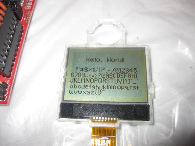
Recently I visited a local cell phone repair shop in search of LCDs with pads large enough to solder. What I came out with was a color display from a Motorolla E370 and a two-inch Motorolla C115 monochrome display. There don't seem to be any datasheets or code examples for the E370 on the internet but I was able to get the C115 running with an MSP430.


The first thing I did was solder wires to the ribbon cable. The pads were wide enough to attach normal breadboard wires to. Soldering them individually turned out to be pretty difficult so I first covered all of the pads in solder then placed the wires on the pads and melted the solder by putting the soldering iron on top of the wires.

To run the display I looked at some AVR code I found on a Russian site and tried to adapt it. The LCD uses the I2C protocol so I looked up how to use the UART module in the MSP430G2553 I was using. The AVR code sends the address of the LCD as a 7-bit address shifted left one bit. When I used this address with the MSP430 the LCD didn't respond and I started to suspect that it was broken. Then I decided to use some code I found from TI that checks to see if there are any devices connected at a particular address and used that to scan all the possible I2C addresses. The LCD responded at an address I wasn't expecting. It turns out that the address was wrong because the UART of the MSP430 expects an unshifted address, whereas the AVR code was sending an address that had already been shifted.

After I had the display running, I wrote a few lines of Visual Basic code to convert a bitmap into a C array. Here is a picture I made to test the display:


Then I worked on a font for the display. There are a lot of 5x7 fonts and not much room for creativity at such a small size but I went ahead and made my own character set anyway. My goal was to make the characters slim so that I could fit as many as possible on one line. As you can see in the picture, the font is variable width since any unused spaces aren't drawn. I also made sure that characters like g and j are drawn one pixel lower.


This LCD wasn't too hard to get running and hopefully I can use it in a future project.

Tuesday, January 22, 2013

Binary LED Calculator

After comparing the new solder joints to the ones I was making with the old iron, I decided to start completely over with the LED Binary Calculator. This time I used DIP sockets and new protoboard I was able to buy when I bought the new soldering stuff. This protoboard is 25 holes wide which is really convenient since each of the eight LEDs needs three holes width. There were also just enough of the old red LEDs I was using before to start over with. The solder didn't take to them very well at the beginning so I had to scrape off a lot of the coating that had formed on it. Because I didn't have a battery holder, I soldered on an 8 pin DIP socket to use as a power connector. I taped wires to a CR2032 battery and I stick the ends into the socket for power.


After soldering everything together I ran a test of the LEDs. They only worked correctly once and the only way to get them to work again was to remove both the shift register controlling the LEDs and the MSP430. Toggling the master reset of the shift register didn't help either. Upon closer inspection it turned out the ground connection to the MSP430 had come loose. I was surprised that it ran at all with no ground connection but I have seen it do something similar on a breadboard too. The buttons worked fine from the beginning except that two of them were linked by a solder bridge. After I fixed that, the whole calculator worked as expected.

Sunday, January 20, 2013

More Soldering Practice

There don't seem to be any local shops that sell good soldering iron tips here. Luckily, though,  I was able to buy a few good ones in another city. I was a bit skeptical when the best tips they had only cost a little over a dollar but I brought them home and they work great! I also bought some good 61/39 solder. Using this instead of the cheap 30/70 solder available locally probably helps a lot too. Later I'll see if any of the cheap tips I have work alright with good solder. I don't think I'll risk using cheap solder with the new tip.

With the protoboard I was using to make the LED Binary Calculator I practiced some more with old soviet chips. Interestingly enough they all have different markings. It was easy to make good solder joints very quickly with my new setup.