 In the last two weeks I have made a lot of progress on my Pocket Calculator. Normally, I like to breadboard everything and have it working 100% before I solder anything, but I had to speed things up since I was leaving home where all my electronics stuff is. So far, the project has turned out reasonably well with only a few hiccups.
Microcontroller: LPC1114
First of all, I had to get out my old LPC1114s and figure out how to program them again, since I haven't worked with them in over 2 years. Like before, it was really easy to do so with an FT232 cable. After frying an MSP430 Launchpad a few years ago by accidentally giving it 5v from the cable, I was really careful about hooking it up this time. One thing I do is leave the cable unconnected from USB until I recheck all the connections, which saved me this time since I had accidentally plugged into the 5v line again.
Looking on the internet I was surprised to see that no one seems to sell the LPC1114 in DIP28 any more. That means the three that I have left might be the last ones I have to play with. There was some sort of announcement a few years ago that NXP would stop producing the chip then they changed their mind after someone pointed out that the company had promised to keep its chips in production. It looks like they might have decided to stop producing them after all, although they are listed as in production until at least 2022 on the NXP longevity page. One interesting thing I found was a listing for the chip in PLCC44 package with 8KB of RAM instead of the 4 the DIP version has. I'm not sure if those ever made it into production but it would be cool to have one to play with.
To program the chip I also had to get GCC running again since I haven't installed it since my computer crashed a few years ago. I moved my electronics folder onto Google drive and the memory mapping preprocessor I wrote for my RPN Scientific Calculator and Programmable RPN Calculator stopped working. I know I can fix it and I won't need it for this project but I can't compile the source for the second one until I get it working again. I also got curious about the various program sections like text and bss that gcc reports on when you compile. It seems that text is the space it takes up in the flash, not dec which I was looking at before. When I get the preprocessor working again I'd like to recompile the source for the Programmable RPN Calculator to see how much room it takes versus what I thought before. I also need to change how the key pad is handled. When I looked back at how I had handled it on that project I realized that I was shorting some pins when multiple buttons are pressed simultaneously. The program section descriptions make more sense to me now that I have done more assembly language. I think that 1k is a lot more than I will need for the stack on this project, so I will definitely change that. Another thing I noticed is that keeping my electronics folder in Google drive causes compilation to fail when the Google background program tries to upload files I'm working on to the cloud. For now, I just shut the program off but I will have to find a better solution in the future.
Power supply
To power the breadboard I dug out the old power brick I found in the junk pile at the hackerspace I used to go to. Even though I had checked when I first found it, I checked again to make sure there wasn't anything strange about that model that would prevent me from using it on my breadboard. One listing for it on Amazon was $200. I hope that is not the real price, since I basically ruined the thing by cutting the head off to stick it in my breadboard. The first breadboard I tried dropped a volt or more, which caused me problems until I figured it out. I vaguely remember having problems with connections on that cheap board before.
For the circuit board I got a 1200mAh LiPo battery from Adafruit. The L4931 voltage regulators I had from other projects drop 0.4v, which will might not let me use the battery much below 3.7v. Instead, I ordered an MCP1700, which outputs 250mA while dropping only 0.17v and also comes in TO-92.

FRAM
After I got the LPC1114 going I hooked up the SPI MB85RS2MTA FRAM chip I got for the calculator. Surprisingly, it worked fine the first time I tried it, which doesn't happen to me very often. Part of what made me decide on this chip is that it can work at 40MHz, whereas the SPI SRAM chips I used on other projects were only 20MHz. If I understand correctly, the LPC1114 running at 48MHz can generate a 24MHz SPI clock. The 12MHz clock I used with SPI RAM on my Programmable RPN Calculator worked fine right away with this chip. There is a second prescaler that I found later I can adjust to get to 24MHz, but I haven't tried it yet. This FRAM chip is only 256k, which is a lot less than the 512k or 1mb flash chips I was looking at, but I think the additional speed and non-volatility will make the trade-off worth it.
LCD
I also went with an Adafruit part for this. At first I thought I would get a 1.44 inch screen to make the calculator really tiny, but I am glad I went for the 1.8 inch screen, since it is almost exactly the width of five columns of buttons. This also worked unexpectedly the first time I tried it. Adafruit provides an Arduino library for the LCD which was easy to get working on the LPC1114. This is the first time I have bought an LCD on a breakout like this and I am pretty satisfied. This one also has a microSD card slot which I haven't hooked up yet. If I run out of space on the FRAM, I will try to free up a pin to control its CS.
When I first got the LCD running, it was drawing at less than one frame per second, which is not fast enough for what I need. I tried adding some delays after the LCD's CS and DC pins are flipped and I was able to get the frame rate up by quite a bit. To make sure the FRAM chip was still working, I tried writing and reading a byte between drawing each frame. One weird thing is that it would miss a pixel occasionally, which remains undrawn at the bottom of the screen. When the next frame started drawing, it began at the bottom where the last frame had stopped. Each missed pixel added an extra lost pixel at the bottom of the screen, which helped me keep track of how often the LCD glitched. Eventually I figured out that the FRAM CS seems to work as fast as the LPC1114 but the LCD CS needs a few dozen cycles to catch up. Suprisingly, the LCD can take data with the same 12MHz clock I was using with the FRAM if the CS and DC signals have long enough to settle. One neat thing I really like about this LCD is that you can set a clipping area and feed data to fill it, which is very handy. When I realized you don't need to toggle the CS line after every pixel, I was able to draw the screen at what seems to be around 5hz.
After I had the battery, microcontroller, FRAM, and LCD soldered to the circuit board, the screen worked fine. Later, I started soldering on the buttons (described below) and connecting wires for the shift register and the display stopped working. This was really confusing since I had not done much that could affect the LCD. I tried changing the SPI clock from 12MHz and finally got the screen to work at around 600 kHz, way too slow for what I need. I tried desoldering the power wire for the button pull ups, disconnecting the SPI clock line from the shift register, and even soldering on new wires for the LCD MOSI and clock lines. What finally fixed the problem was making the software delays for the LCD CS line longer. The only thing I can imagine happened was that the original delays were barely long enough and the small changes I made to the circuit somehow necessitated a few more cycles delay.
Key pad
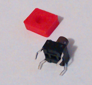
One of the biggest challenges in previous calculator projects has been an effective keypad. This time I had plastic caps 3D printed at my university. In general they turned out really well, although they are not exactly the same size and shape due to the tolerances of the printer. One of the people who works at the university helped me a lot with printing them and recommended I design them in OpenSCAD.

The buttons themselves come from Grayhill. A few other people have mentioned liking their buttons and they were also really cheap at Mouser. I ordered a 7mm and 9mm tall button to see which one fits better and the 7mm one leaves what looks like a little over a millimeter between the body of the button and the bottom of the key cap. I used epoxy to attach the caps and the extra room let me scrape any extra epoxy off of the button stem with a paper clip when I glued them on. My plan at first was to glue the caps on then put the button on the circuit board so I could rotate the caps and line them all up before the glue dries. After I did the first few I realized that the posts spin in the hole. This saves me from having to line them up but also means they quickly get unaligned when you press them. This is one of the things I am glad I learned, since part of what I wanted to accomplish with this calculator was perfecting hardware and software I want to use on later calculators. Overall, the keys seem to work well, although a few don't slide down as smoothly since they still have epoxy residue on the stem.
 |  |
Circuit board
I decided to use headers and stack two circuit boards with components between them. Unfortunately, this did not leave enough room to add sockets for the chips, so they are soldered directly to the board. My first plan was to use a 5x7 key matrix but I added an extra row of keys to make room internally for the battery. I should have done better planning and gotten a smaller battery but I am also glad to have some extra keys. The width of the board also ended up bigger by two columns of holes, but this turned out to be useful as well when I soldered on pull ups for the rows of keys. The two boards are held together by headers I got from Mouser. They look similar to what an Arduino uses but where almost impossible to separate after I put them together long enough to solder everything. I am leaving them only half plugged in until I am totally positive I don't need to solder anything else.
Initially I wanted to route the signals to the keys and LCD on the top board through the headers, although it seems to take up less room just soldering wires directly between the halves. This way it opens like a book when I need to access the inside. The wires, which I took from an ethernet cable, are surprisingly stiff and I am a bit afraid that bending them too much to open and close everything will weaken or break them. I had forgotten how well 30 gauge wires worked before and I should have used that. For the keyboard I bought 7 feet of telephone wire and used that instead of ethernet wires. It is extremely flexible and a lot thinner. It is also stranded, which I have read is not good for digital signals, but since I am only using it on the key pad, it should be fine.

The battery is held down with right angle header pins. The charger I got from Adafruit came with an extra charging wire which I connected to the board so I can charge the battery without having to remove it. The on/off switch is a simple switch I had lying around which I mounted at an angle. I had just enough room to add a tactile switch next to it so I can put the LPC1114 into programming mode. At the bottom, I added headers for the FT232 cable along with a row of female headers to guide the cable in so I don't misalign the rows and destroy everything with 5v again. Hopefully, I will also be able to use the cable for communicating over UART so I can update the FRAM without flashing something to the microcontroller that just writes new information to the FRAM. The last part is a 74HC165 which I need to read the key pad. Usually I would not solder a chip on the board without testing it on a breadboard, but I have used the chip enough to be comfortable with it.

Conclusion
The next steps will be getting the UART going, reducing the LCD delays so they are faster but still reliable, and fixing the key pad reading code, which only recognizes rows at the moment. After that I can focus just on the software.
No comments:
Post a Comment