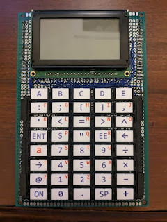
As part of all the keypad tests for my presentation at the 2023 Hewlett-Packard Handheld Conference, I built a keypad and new hardware for my 6507 Graphing Calculator. The keypad itself is laser-cut white acrylic with dye sublimated labels. A local business cut the acrylic for me since I didn't have my laser cutter yet. My design for the laser cuts left a tab at the top of each key so it would stay connected to the larger piece for applying the labels. The remnants of snapping the keys off their tab are visible on the top of each key. The keypad itself is not that great since the keys on the left and right edges don't flex enough and need a lot more pressure to actuate than the other keys. I made sure to add extra space on the edges of the next keypads made on my laser cutter so the keys can flex enough.
The original board for this project got pretty cramped toward the end of soldering it. There was no separate address or data bus space on the board, so bus lines were soldered directly from the pins of one chip to another. This saved a little bit of room but was harder to keep straight as I added more chips. The new board (below left) had a dedicated area by the oscillator on the bottom left for all the bus lines which is much cleaner. One tricky thing about the new board is that the buck converter on the top left never put out the correct voltage so I ended up using a separate module (not pictured) from Adafruit. It would be nice to find a switching power supply chip that works reliably on protoboard, but I'll stick with modules like these for projects that need a lot of current for now.
One problem that took a long time to debug caused the system to crash intermittently. It seems the little protoboard standoff for the EEPROM visible above in the photo on the left was causing the problem since the system worked reliably once the EEPROM was seated in the socket without it. The point of the standoff originally was to make it easier to take the EEPROM off the board and put it in the programmer without risking damage to the pins. It's not clear if the connections were flaky from the standoff or if the header pins the standoff uses had stretched out the socket.
To help plan out the board, I made a Python script that reads in a text file describing the location of the chips and the connections between all the pins. It generates an SVG image of the board and uses JavaScript when embedded in HTML to show interactively which pins are connected. Mouse over the image below to see how it works.
The new board's EEPROM is 32K compared to just 8K originally. It would have been a neat challenge to fit everything into 8K, but the firmware has already hit 9K without any graphing abilities, so I decided to just add a larger EEPROM in an effort to finish the project. Since the 6507 processor can only address 8K, the EEPROM is split into eight 4K banks. The mechanism to do this is in place, but the calculator hangs when trying to execute code after switching banks. I ran out of time on this bug before my HHC presentation and hope it won't be too difficult to solve when I get back to it.
One thing I've thought a lot about for the past few years is running the code for this calculator on a microcontroller in emulation. This was part of what got me interested in building my Blinky Robot which runs 6502 code on a PIC32 in an emulator written in MIPS assembly. Last year, as the time was getting close to packing up my laser and losing access to it for almost a year, I worked on building the new hardware for my Tiny Calculator as well as an emulated version of this calculator. So far, it only draws a test pattern to the screen and recognizes key presses. It should be easy to get the emulator up and running since it uses the same PIC32 as the Blinky Robot.
The calculator runs on three AAA batteries, so the case is triangular with the batteries in the back behind the LCD. This shape was surprisingly hard to design and print on my 3D printer. The case needed to be printed several times to make sure it lined up with the circuit board. There is a slot in the side to provide access to a breakout board with the PIC32 on it. Rather than try to get that correct down to the millimeter and match the protoboard, I cut a hole in the case then printed and glued on a cover piece so the hole edges would look flat. It was also relatively difficult to get the circuit board to stick to the triangular case with slanted header pins stuck into slots printed in the case. The final version has a very tight fit so it won't come apart but this also makes it difficult to change the batteries. I'll have to rethink the design if I build another one like this.


No comments:
Post a Comment