Thursday, June 27, 2019

New Project: 6502 Calculator Emulator


In my post about Open Projects, I mentioned this project, and now I'm officially announcing it. This is a JavaScript based emulator of the 65C02 processor that runs in the browser. My plan is to write assembly and load the assembled binaries into the emulator where I can test them. Eventually, the page will be hosted on a public site where other people can try the software for the 6502 calculator I'm working on and report bugs.

Before I started on this project, I looked at a lot of other browser based emulators hoping I could use one of them. Some are unbelievably slow, working at way less than 1MHz and would not work well to test the calculator code that will eventually run at at least 10MHz. All of the emulators I looked at also lacked bank switching. The calculator will probably need several hundred kilobytes of memory which none of the emulators provide. The last reason is being able to map the peripherals into memory how I like and have them resemble the actual physical calculator I'll build when the software is finished.

The slower emulators I looked at do the emulation and interface in one thread as far as I can tell. Doing the emulation in a second thread with a Web Worker is a huge performance increase. In my emulator, the emulation thread performs a set number of instructions then checks in with the interface thread to get keyboard input and relay new screen contents. Setting the number of instructions to 1,000,000 yields around 70MHz performance, which is five times faster than the actual chip. It also makes typing a little unresponsive, so I set it to just 100,000 which is a good balance between responsiveness and performance of around 20MHz.

The emulation code ended up fairly compact. This is my first JavaScript project, and when I showed it to someone asking for advice, he said it looked like low-level C code. Each addressing mode has its own function and each operation (ADC, AND, ORA, etc) has its own function. The functions for the instructions themselves are very short since they are mostly combinations of those two types of functions. Rather than a switch statement, I use the op codes to index into an array of functions, which is probably a lot faster. This is how I would do it in C and it works in JavaScript, although the guy who was helping me pointed out that there are higher level structures in JavaScript that you could use instead. Banking works by splitting the first three 16k segments into banks (minus the first 200 bytes for zero page and the stack) and leaving the fourth segmented unbanked since it will always be EEPROM.

The first thing I tried when I got the emulator working was the test suite by Klaus Dormann. It passed after a few modifications, mostly to memory address wrapping. Then I mapped two banks of RAM to a simulated 256x128 video output where each pixel is represented by one byte. The final calculator might be black and white or have less color resolution, but I'll use this for now. I made a simple font which is copied to the display memory pixel by pixel. This didn't look especially impressive, so I found a much better looking one online to use instead. Next I added support for transparent backgrounds.

I got EhBASIC running after a couple days of fighting with it. The first command entered would work and the second would fail with "Syntax Error" depending on what the command was. I tried all kinds of things to find the problem, including stepping through the code to evaluate input, before I tracked it down to a location in zero page. It looked like one of the bytes there holding interrupt information was somehow corrupt since the error was thrown after it was evaluated. The source listed a handful of zero page bytes as free to use, so I put the pointer for updating the screen there. As it turns out, the byte is not actually free! Everything worked fine after I moved the pointer somewhere else.

Tuesday, June 25, 2019

More Calculator Processors

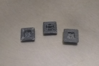
Last year I wrote a post about a lot of different processors that could be used to make a calculator. Recently I decided to buy some of them from the CPU Shack Trade List and found some others that might also work. John, who sold me the chips, was really helpful and sent everything very quickly.


These are the processors from the last post that I got examples of:

CDP1806ACE
E87C196KDH20
N80960SA-16
N80C196KC16
NS32FX164V-25
TMS320C25FNL

The really exciting one is the NS32FX164. It seems like a really neat chip, and I was having trouble finding any of the NS32FX160 series chips to play with. There are a lot of variants built on this core, and this seems like one of the best ones to have. The instruction set is really interesting since there are so many options and extensions. This is definitely a CISC processor.

These are new chips not covered in the last post:

2650AN - This is an 8 bit microprocessor with more registers and instructions that a 6502. However, it has a strange 13-bit address system that makes it less useful than all the other processors that can address at least 16 bits. The one I got is the A version which is missing some of the added instructions of the B version. Top speed is apparently 1.25MHz.

INS8073/N - This is another 8 bit chip that that also has limited addressing potential. The main appeal of this processor is that it has a version of BASIC built into ROM. I don't think I would rely on that for the calculator's main language, but it might be neat to have it as an option to play with. Hopefully there is a way to boot from external memory and jump into BASIC later.

L3903-57 - This is part of an offshoot of the 6502 family that was used as part of modem chipsets. It has a lot of microntroller features like internal RAM and peripherals like timers. It runs at up to 20.5MHz, compared to the 8MHz of the 6502 derived microcontroller made by WDC and the 14MHz of a 65C02. It is not entirely compatible with the 65C02 since it handles indirect jump instructions differently and has additional instructions for threaded code. It might have more flexible timing constraints, which could be helpful even if it isn't running at top speed.

N8X305N - This is the weirdest processor in the list by far. It has a 16-bit wide instruction bus but no dedicated bus for data. External data access can only be conducted through two "ports." The really strange thing about this chip is that it only has eight instructions. The OR instruction, for example, has to be synthesized from AND and XOR. It seems like it would be a big challenge to write assembly for this.

SAB80199 - This is a neat 16-bit chip made by Siemens. Unfortunately, I can't find a datasheet for it, so I'm not sure yet if it would work well for a calculator. I paid to access the datasheet database at eca.de, but the link they sent was broken. Hopefully they will respond to my messages soon.

As I wrote in my another post, I'll have to finish some of the projects I have open now before I start on something with one of these chips.

Monday, June 24, 2019

Tiny Calculator: Keypad

The last few weeks I have spent a lot of time on the keypad for my Tiny Calculator project and the results are a little surprising! After considering a lot of different ways to make caps for the keys, I finally bought a 3D printer, specifically an Ender 3. Before that, I tried using an Xacto knife to cut out a base and a slightly smaller square post from PVC I bought at the craft store. The result was pretty uneven and there didn't seem to be any way to make them all exactly the same size, so I bought the 3D printer the same day. It was easy to put together and has produced great prints from the very first time I tried it!

The first thing I worked on was designing a button cap with a skirt that would keep it from falling out of a grid overlay. It was really easy to do in OpenSCAD. I printed several versions to get the dimensions right and design a hole in the base so it would fit over the posts of the tactile switches. The first version was black and looked really nice. Next, I started on the overlay and experimented with several versions. One that was only 0.5mm thick fell apart when it came off the raft it was printed on, and I eventually settled on 1mm for the thickness. As I experimented with improving it, I added supports that fit over the header pins on the keypad to keep everything straight and holes for longer pins to keep the grid attached. This worked really well to keep the keys straight and attached but the grid was still a little flexible because it was so thin, so I added a 3mm wall around the edge which made the print very rigid.

The buttons themselves were printed with the holes for the posts facing down. The slicer program inserts tiny supports to keep the hole from collapsing while the button is being printed. It took a long time to carve the supports out and the results ended up being a little uneven. Some of the holes were slightly too deep and the entire button post fit in them with no clearance for the button to be pressed. This led some buttons to have a stronger click and some to stick up farther than the others. One thing I tried to make them more even was to print them in rows of five with the hole facing up. The hole depths all turned out extremely uniform but the lip holding them together came out garbled and they easily broke apart since the lip had to basically be printed parallel to the ground with no support. The next time, I turned the row of five on its end, which worked since I had removed the lower skirt edge to make room for the lip holding them together. Printing five of them in a row like this makes the button presses more uniform and the rows straighter.

The design for the keys labels was done in Google Sheets and copy and pasted into Paint. This worked really well! It was way easier to make modifications and keep all the text uniformed and aligned than doing it in Gimp, which I tried a few months ago. Once I had the design, I went to Staples and had them printed on overhead transparencies. Unfortunately, there is no way to print in white on a standard printer, so you couldn't see anything when the labels were put on black buttons. I bought a roll of white plastic and now the labels look exactly how I planned. For the next iteration, I bought a cheap inkjet printer and transparency paper so I can make the labels myself. They are printed in reverse so I can glue the ink side down and avoid smudges from finger presses. I designed and printed a little bracket for cutting out the labels at exactly the right size, but it turned out not to be useful. Super gluing all of the labels on took a couple tries to get right, but I'm very happy with the result! Now that I have the 3D printer, I plan to make similar keypads for some of my other projects.

Test button made from PVC

Different versions of the button cap

Under side of the button caps. The middle one still has supports.

Failed 0.5mm overlay print

1mm overlay print

Overlay with added wall for stability
Failed print of five connected buttons

Successful print of five connected buttons

Bracket for cutting out labels

Keypad labels


Monday, June 10, 2019

Open Projects

After starting on my 7400 Calculator project, I thought about how many projects I have open at the moment. Like a lot of hobbyists, I seem to start more than I finish. Most of these are not abandoned, since I do plan to get back to them someday. I decided to take stock here of how far I am and what is left to do. There are two projects here I have not posted about: 6502 Optimizing Assembler and 6502 Calculator Emulator. There isn't really enough yet to write about, but I might as well mention them since I have been working on them now and then for a while. They would also be good for the github page I want to set up and list when I apply for jobs. My plan is to finish most if not all of these projects before I start on something else. Otherwise the list might keep growing without finishing any of them.


Tiny Calculator
80%
A few weeks ago, I put a lot of work into the interface code, which ended up taking more time and effort than I imagined. Like in my RPN Scientific Calculator, the interface code takes up a lot of space compared to the math routines. So far, I can enter numbers and do addition and subtraction, but I still need to fix the sign of the result. For the rest of the calculations, I need to write a lot of checking code for things like scaling angles before applying trig functions and avoiding inputting negative numbers in logarithm functions. Two weeks ago I made some major progress with the keypad, which I will post about soon.

Posts related to Tiny Calculator


Pocket Calculator
20%
This project kind of stalled because I got busy with other stuff and also because I hit a few hardware problems that I did not solve. The LCD would work when the speed of the SPI clock was set very low and it would continue to work once I turned the speed up to what the LCD is rated for, but if I turned the calculator off, the LCD would not work again until I set the speed back to very slow. The LCD also did not work when I fully closed the case. Eventually, one of the very stiff ethernet wires I was using broke right off. I will need to rewire the LCD with different wire and start over on the emulator I was working on.

Posts related to Pocket Calculator


Programmable RPN Calculator
95%
The last time I worked on this calculator in 2015, I considered it finished other than labels for the keypad. One thing I figured out in the meantime is that the key reading is not entirely reliable since two of the pins on the LPC1114FN28 are open drain, which I did not account for. It also seems that I did not write the key reading code correctly, so there is a chance of shorting pins when you press two keys at once. These probably won't take long to fix, then I will make labels for the keypad, which should be easy now that I have done it for my Tiny Calculator. Another thing that might be helpful is to review the source code and make sure all of my checking code is correct.

Posts related to Programmable RPN Calculator


7400 Logic Calculator
30%
This is my latest project and I have been doing a lot of work on it, so I am still really excited about it. I might try to finish some of the projects that are close to done before I return to this to get them out of the way.


6502 Graphing Calculator
???
In summer 2015, I put this calculator together very quickly to try to get it ready for Makevention that year. Not suprisingly, it did not work at all since I was in such a hurry putting it together. I'm not sure it would be worth it to resurrect this project, but I would like to at least return to it and figure out why it didn't work. One possibility is that the LCD was damaged when I was trying to drive it with an MSP430 since the wires I used had metal connectors that kept shorting to each other. Another thing I noticed when I pulled the board out a few weeks ago was that the EEPROM is not a modern CMOS chip but something older that uses 140mA and has a slow 250ms access time. The latches to drive the LCD are 74LS874s, which I now realize consume way more power than HC chips. There could also be other problems like the CPLD. In any case, it will be fun to try to figure everything out.

Posts related to 6502 Graphing Calculator


6502 Optimizing Assembler
25%
This is a project I started to practice my Python skills and have a concrete project to talk about in job interviews. My plan is to analyze assembly files (not compiled binaries) and make optimizations based on a few simple assumptions. This will should be able to shave a few cycles off of unneeded instructions, which is especially useful when you are using macros. It will also be able to manage zero page much better than just assigning fixed addresses to each function or sacrificing the X register for use as a slow pseudo stack.


6502 Calculator Emulator
40%
This is a 6502 emulator written in JavaScript that will let me test calculator firmware in the browser without having to upload it to a physical calculator. The emulation works at over 50MHz currently and passes Klaus' test suite. The input and screen output work, as well as memory paging like the real calculator will have. Now I have to find a way to speed up screen drawing, since I think this is the source of lag when typing. Then I will need to start writing the firmware for the calculator. Someday I will host it on a website so that other people can help me find bugs.

Thursday, June 6, 2019

7400 Logic Calculator: Breadboarding

In April, I made a lot of progress on my 7400 Logic Calculator project. The last month or so I have been focusing on other projects (which I will post about soon), so I wanted to make a post about this project while everything is relatively fresh on my mind, since I might put the project on hold for a while.

Since the last post about this project, I have made two major design changes. First, I did exchange the 74HC574 octal latch I was using as a register for 74HC670s as I mentioned in that post. The one latch I was using for the ALU is not enough since I need a second register to hold the second operand for the ALU and a third to hold the flags like carry from the ALU. Since the latches come in DIP20, three of them takes up about as much room as four 74HC670s in DIP16, which give a total of eight 8 bit registers. This will give way more flexibility for memory pointers and other uses that will speed things up and make programming easier.

The second change is to the program counters. Instead of saving a copy of the PC in its own register so that it can be reloaded later, the PC is loaded directly from the data bus. This is a little less convenient but became necessary when I thought through how to handle indirect memory addresses. The address latches for the SRAM are loaded from the PC, which is an idea I borrowed from the CSCvon8 project. It is also a minimal design and with less than 20 chips is a lot smaller than my design. One neat thing I found out about corresponding with the owner of that project is the 74LS593 counter which saves room since it is an 8 bit counter in one chip (most others I have found are 4 bit). This is the only 8 bit counter with load inputs that comes in HC. I ended up not using the chip since it doesn't have separate input and output lines, but I did order four of them from China while I was considering it. They look very new and shiny and are marked simply "JAPAN" rather than "ST," which is the only company I could find that ever manufactured them, so they are probably fakes. One day I will test them out and see for sure.