Sunday, December 25, 2022

2023 Project Goals

2022 was another year full of all kinds of fun projects like my 7400 Logic Calculator plan, Interactive 6502 Assembler, and embedded programming on Linux. Although these weren't on my list of 2022 Project Goals list, I did learn a lot from them and make progress towards some of the goals on the list. With 2022 coming to a close, it's time to take stock of my progress from 2022 and set some goals for 2023.

2022 Project Goals

6507 Graphing Calculator - Still working
Despite another year of work on this project, there is still a lot of work left to finish it. The plan to reduce the firmware size to fit into an 8K ROM by using a Forth VM didn't work out as expected. After a little more work, I plan to post about my progress on this from 2022 and how the project will proceed in the future.

This is the one project from the list that is completely finished. It even made it onto Hackaday yesterday! As mentioned in the article, what I learned from this project will be useful for other projects like the PIC32 Calculator below.

Tiny Calculator - No progress
Not much to say here. There just wasn't enough time to get to this one.

PIC32 Calculator - Still working
Although I haven't started on this project formally yet, a lot of my projects from 2022 will help me work on this one. As mentioned in the last project goals post, this shouldn't take as long as other calculators since it won't be necessary to write all the firmware from scratch.


2023 Project Goals
This year, my goal is to finish enough projects to give a presentation at the Hewlett-Packard Handheld Conference (HHC) in fall 2023 like my presentations at HHC 2019 and HHC 2021. This will take a lot of focus which I wasn't able to pull off last year. Hopefully, having a firm date and goal in mind will motivate me. Here is the tentative list of topics:

Although not a calculator, this should be really interesting to present on since the 6502 emulator written in MIPS assembly can be used to emulate 6502 calculator firmware on a PIC32. This is a good one to start with since this project is already finished.

As mentioned above, there is still a lot of work left to do for this though I know exactly how to proceed from here. Barring any unforeseen complications, this should be a straightforward project to finish. This will be one of the main topics of the presentation.

Calculator key comparison
This is another topic where I made a lot of progress in the last year but haven't posted anything yet. My goal is to compare many different ways of making calculator keys using 3D printing, laser cutting, cast plastic and other methods.

PIC32 Calculator
This is the same project from my list last year. This will be the most exciting thing to present on if it's ready in time. 
 

Monday, December 19, 2022

PIC32/6502 Blinky Robot

The PIC32 robot from my 2022 Project Goals is finally finished! Building it was a fun way to learn about the MIPS architecture and programming the PIC32. It was also a chance to work on a 6502 emulator that will be useful for other projects.

As far as robots go, this is not a very useful one since all it does is blink its eyes every few seconds. The interesting part is how it does the blinking. Rather than switching the LEDs on then delaying a while before switching them off, the robot runs several layers of emulation with the innermost emulated system blinking the LEDs as fast as possible. All the layers of emulators within emulators combine to produce enough overhead to slow the blinking down to a rate that is visible.

Sunday, December 11, 2022

Tali Forth 2 on Linux

When people on IRC have questions about Forth or I can't remember how a particular word works, it's nice to have a Forth handy to try things out on. For this, I usually open Tali Forth 2 in a browser window on my website. Even though it's a 6502 Forth running in a JavaScript 6502 emulator rather than a native x86 Forth like Gforth, it works just fine for experimenting. Since most of my programming is on Linux now, it seemed like a good idea to have a way to do my tests in a terminal.

There were several choices for getting Tali Forth 2 running on Linux. One of the easiest ways is to use an existing emulator like Py65 since Tali Forth 2 comes with a pre-compiled binary ready to be emulated. However, this was less interesting than using one of my own emulators. Another option was the JavaScript 6502 emulator running on my website. As mentioned in the post about my 6507 calculator, this also runs in a terminal thanks to node.js. Another option was to extract the emulation engine from my 6502 Interactive Assembler, although it seemed this would be time consuming to untangle since the emulator was not designed to work without the assembler. In the end, it was the most convenient to use the 6502 emulator written in MIPS assembly I've been working on for another project using the tools mentioned in my post about MIPS development in Linux. As mentioned in that post, a binary compiled for MIPS will run right from the Ubuntu command line as if it were native thanks to QEMU and also have access to the terminal through Linux syscalls. Going with this emulator was also an opportunity to double check my MIPS code emulates the 6502 correctly.

Wednesday, December 7, 2022

MIPS Development on Linux

Two of the projects from my 2022 project goals use a PIC32 microcontroller. The company that makes them, Microchip, offers an IDE and a compiler which is a port of GCC. The free version of the compiler has some limitations which would make it difficult to finish one of my projects. However, since the PIC32 is a MIPS core, I was able to set up some tools on Linux as an alternative.

The two main limitations of the Microchip compiler are that it doesn't allow GCC's -O3 level optimizations or compile to the MIPS16e instruction set unless you pay for the full version. The loss of MIPS16e is a real bummer since it saves a lot of program memory by using 16-bit instead of 32-bit instructions like ARM's Thumb instruction set. Microchip claims that programs in this format are 40% smaller without losing much performance which would be great for one of my projects. The standard MIPS GCC has none of these limitations, but it also doesn't come with any headers or other files specific to the PIC32. This got me thinking about how I could combine the two tools and use MIPS GCC on Linux to generate part of the program. Running a few tests shows that Microchip's compiler will accept assembly files written for either the 16-bit or 32-bit instruction set, and the linker will accept object files for either instruction set too. This way, all the chip specific parts of the program like initial setup can be compiled with Microchip's compiler while the bulk of the program can be compiled externally with optimizations and linked in later.

Saturday, July 30, 2022

7400 Logic Calculator: One ROM Design

After finishing the new design for my 7400 Logic Calculator, I continued to think about different ways to build a minimal design that would fit in a calculator body. Watching James Sharman's videos about his breadboard computer got me thinking about eliminating the microcode sequencer ROM, which would save a lot of room. It eventually dawned on me that the ALU ROM could be eliminated too if it was combined with the program ROM. ALU operations then become ROM lookups and can share the same circuitry used for looking up constants which also eliminates chips. Based on this, I came up with a modified design using only 18 chips compared to the other design's 21. Best of all, the whole thing fits into just one 32K EEPROM rather than three.

Sunday, July 10, 2022

6502 Interactive Assembler

One of my 2022 Project Goals is a PIC32-based robot which emulates a 6502. While working on the emulation, I kept having to look up details about address modes and flags, so I made a Python program for Linux called i65 to look up information like the addressing mode, size, cycle count, and flags for 6502 instructions (GitHub link). It can take an instruction name or addressing mode as an argument and displays information for any instructions that match.

If the program is started without any arguments, it waits for input and shows all instructions that match what you type until it's narrowed down far enough to show the full information. The Kowalski 6502 simulator has this, and I wanted something similar for Linux.

Thursday, May 19, 2022

7400 Logic Calculator: Revisited

In January, I made a post about my 7400 Logic Calculator project coming to an end and my ideas for improving it. After thinking about the project again this past week, a lot of new ideas came to me for fixing most of the problems with the last design. The new design also incorporates a lot of the ideas from the last post. As I explained in another post, my plan is to focus on a short list of projects for 2022, so I decided to document my ideas for the new design rather than restart the project.

Architecture
The new design is a 4-bit architecture rather than an 8-bit architecture like the last version. One thing that complicated my ideas before was trying to figure out how to drive the ALU with a register and another source, latch the ALU output, and write it to the correct place. The new design handles this by using two 74HC670s as 4-bit register sets feeding the ALU directly to avoid the complication of having the ALU on the bus so other sources can drive it. As a result, anything that goes through the ALU needs to be loaded into a register first, which is not a big sacrifice since the two 74HC670s provide eight 4-bit registers. Latching the ALU output also simplifies the design since an instruction only needs to read or write to the ALU but not both in the same instruction. A 74HC574 latch can optionally be trigged to capture the carry bit of the latched ALU output so it can be fed into the next ALU operation.

Other than the ALU and set of four register pairs, there is a 74HC193 counter that supplies the bottom four bits of the address for an 8K SRAM. This register is named X. The next eight bits are supplied by a 74HC574 "RAM pointer." It's a little unconventional to address the memory this way since it splits it into 256 pages of 16 bytes each. However, 16 bytes is the right size for holding floating point numbers, so the memory can be seen as holding 256 objects with the RAM pointer specifying which object. As a bonus, an instruction can trigger the clock input on the X register to count up, saving a few cycles when stepping through memory.

The next part of the system is a 32K EEPROM to hold the program along with four 74HC193 counters to act as the program counter. This is a pretty standard setup. The RAM pointer and X register combo mentioned above drive the EEPROM address through pullups when the program counters are disabled, so constants can be loaded from the program through a 74HC574 latch. Another latch captures instructions from the EEPROM, and a 74HC244 buffer transmits keypad input to the bus. There is also a control signal for an LCD which is connected directly to the output of the two register sets.

Sunday, February 6, 2022

Electronic Birthday Card

For my friend's birthday, I made her a theater-themed electronic card that sings happy birthday. The outside looks like a theater announcement, and the inside looks like a movie marquee. My girlfriend printed both graphics on a Cricut machine, and they look much better than what I could have come up with myself.

The hardware is pretty simple. The top part, which flips up to show the marquee, is a simple 3D-printed box. My original plan was to use the box as the bottom part to hold the battery and electronics. After waiting six hours for the part to print, I realized it wasn't tall enough to hold the LEDs of the marquee, so the part became the lid instead of the base. For the bottom part, I cut a piece of plexiglass from the hardware store and printed standoffs to attach it to the circuit board. This was my first time working with plexiglass, which turned out to be very easy to crack or break while working with. It's neat to have some experience with it in case another project needs a plexiglass case.

The movie marquee inside has 20 LEDs in total around the edge. They are arranged in five groups of four LEDs with an NPN transistor controlling each group. The groups are interspersed so that each fourth LED is in the same group and shares the same brightness. The blinking pattern rotates clockwise with the brightest LEDs in the front of the pattern so the other LEDs look like they are fading and trailing the brightest one. This looks better than just lighting up one group at a time. The brightness is controlled by simple software PWM running on an MSP430. A timer fires every 1,000 cycles giving 16,000 steps per second since the microcontroller runs at 16MHz. Every time through the loop, the code to adjust the PWM executes then blocks on a while loop waiting for the timer to finish it's 1,000 cycles. This keeps the brightness uniform since a step always takes the same amount of time regardless of how long the PWM code needs.

16,000 steps per second is way more than needed to adjust LED brightness. The extra granularity is useful for controlling the small piezo buzzer that plays happy birthday. The music consists of simple beeps from the speaker, which only takes a few dozen bytes to store and has no problem fitting in the MSP430's flash. The music notes start out as raw frequency values beginning with A at 440Hz. A series of C macros let me calculate how many steps each note needs including a short bit of silence at the end of each one. While I try to avoid overreliance on macros, in this case they really helped list everything in a clear way. Specifying the notes to be played was then very easy:

const unsigned int music_notes[]={

    NOTE(NOTE_C,EIGTH),
    NOTE(NOTE_C,EIGTH),
    NOTE(NOTE_D,QUARTER),
    NOTE(NOTE_C,QUARTER),
    NOTE(NOTE_F,QUARTER),
    NOTE(NOTE_E,HALF),
    ...
    MUSIC_END};

My first try at playing notes in a scale was noticeably off, and two of the notes had the same tone. It took some investigating to figure out that the way I had the timer calculations listed based on the frequency was rounding the highest frequency notes down to a small integer which was between two recognizable notes. This is what lead to the two notes sounding the same since they'd been rounded to the same value. One helpful thing I've started to do since getting interested in assembly language is turning on listing files in the compiler to see what assembly is generated. This showed that the values calculated where way too small, which I double checked with Compiler Explorer. Listing files are a great tool that have helped me solve several bugs like this. After adjusting the calculation macros, the notes sounded just right, and happy birthday played correctly. 

Soldering everything together was a bit of a challenge. The top PCB with the LEDs has the paper with the happy birthday graphic attached to it, so none of the wiring for the LEDs could go completely through the board since they would have to penetrate the paper too. Instead, all of the wires and resistors are soldered flat on the back. This is a technique that might come in handy someday for something else.


The MSP430, transistors, and buzzer are on a small separate PCB sandwiched between the top PCB and a piece of plexiglass. The battery pack and on/off switch are attached to the plexiglass with hot glue. Although I've never been very impressed with the durability of hot glue, whatever type I got from the craft store this time is absurdly strong and was more than good enough for this project.

Wednesday, January 5, 2022

2022 Project Goals

Though I haven't made many posts in the past two years, I have been working on projects slowly but surely. As time passes, I realize how important it is to focus on a small number of projects so that some of them eventually get finished. For 2022, I'd like to pick exactly which projects I want to finish. Hopefully this will motivate me and help me focus!


Main projects

6507 Graphing Calculator
This project is still going after 18 months of work. While I haven't made any progress on implementing the new firmware features I mentioned in my last post on this, I have been working a lot on a subproject for verifying the calculator's floating point routines. Like many projects, this took a lot more time than I expected. Hopefully, I'll be done with this subproject soon so I can post about it. I've also been working on a way to make nice plastic keys for the calculator.

PIC32 Robot
This is an idea I've had for a long time for a simple "robot" built using a PIC32 microcontroller. It's a really interesting project that shouldn't take nearly as long as the calculator projects. It will be a good opportunity to get familiar with PIC32s which I want to use for a future calculator project. Hopefully, I can devote a little bit of time to this and still have time to finish or at least make good progress on the 6507 Graphing Calculator this year.


Other projects

Tiny Calculator
Since the 6507 competition began in 2020, I stopped working on this calculator. In the unlikely event that I finish the 6507 calculator this year, I'd like to return to this project and make some major changes. First, the floating point routines need to be redone using proper guard, round, and sticky like I learned how to do for the 6507 calculator. The existing Tiny Calculator firmware doesn't round in a conformant way and instead uses 32 decimal places to try to mitigate the rounding errors. Also, the routines use 9's complement as TI shows in their documentation for BCD subtraction. It became clear after writing most of the firmware that this wasn't the right way to go, but I didn't have the heart to rewrite everything. My plan now is to take as much as I can of the existing firmware and write a library of BCD floating point functions that use 10's complement with 12 decimal places and proper rounding then call those functions from C to rewrite the Tiny Calculator firmware. I'd also like to find a better solution for the keys and case.

PIC32 Calculator
This is another project I have thought about for a long time. This should be much simpler to tackle than my other calculator projects since I won't be writing the firmware from scratch. If I'm able to finish my two main projects this year, this is another one I'd like to start working on.

Tuesday, January 4, 2022

7400 Logic Calculator: Project End

After two and a half years of on and off work, I'm ready to end this project. Unfortunately, I got distracted by other things and never got close to finishing the project. When I last worked on it, the calculator could step through program memory, load immediate values, and move values between registers. The ALU in the form of a DIP8 SPI EEPROM was programmed but never hooked up to the rest of the circuit. A few months ago when I moved, I finally took apart all the breadboards, so the calculator is officially gone. Below are some ideas about what I would like to keep and what I would like to do differently next time if I ever return to this project. Over the past few years, I've thought a lot about how to redesign this, so I may change my mind again. These are the ideas I have so far.


What to keep

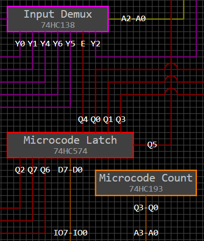
Control signals in instructions
Like most other TTL computers, this one used an EEPROM to store the microcode controlling the state of the components in the system. Since the instruction byte is just an arbitrarily assigned index into a lookup table, I also encoded information in the instruction itself. This let me save room in the design and is part of how everything fit into one microcode EEPROM instead of two.

Work on both sides of the clock
An inverted copy of the clock signal latches values where necessary so that state changes in the circuit when the clock signal goes up and is latched when it goes down. This is simpler than trying to coordinate machine cycles like a Z80 or 8051.

Separate RAM and program memory
As tempting as it is to build a Von Neumann architecture where addresses can refer to RAM or ROM, it's simpler to keep the two types of memory apart.


What to change

Move from 8-bit to 4-bit architecture
This is the biggest change since it affects a lot of the other aspects of the design. It will hopefully require fewer chips and simplify some things. In the old design, for example, there were four 74HC670s that form two sets of four registers for a total of eight 8-bit registers. In the new design, one 8-bit latch should be enough to hold two 4-bit registers. This is also a good register size since the BCD numbers a calculator uses are divided into 4 bits for each decimal place. 

Simplify design
The old design was up to over 30 chips without being finished. Space on the two protoboards I planned to put the chips on was starting to get really tight. The new design should be simpler since it only uses 4-bit registers and also because I have some new ideas for reducing the chip count like using pull ups to eliminate a lot of buffers. For example, to load immediate values into one half of the 8-bit latch that holds the two 4-bit registers, the immediate value can be encoded in the instruction and fed to the data bus with pull ups. Z-stating everything that can drive the data bus and loading the latch will load the immediate. The other 4-bit half can drive the other four bits of the data bus so the load retains the value in the other half of the latch. Another idea is to use pullups to the RAM address bus driven by the bits of the instruction to refer to eight or 16 bytes of RAM that can be used like registers.

Arithmetic Logic Unit (ALU)
My plan to use a DIP8 EEPROM as an ALU was something novel about the old design but at the same time also what held me back from finishing it. The EEPROM I found had 4MB of storage, so it could hold 64 tables 8x8 in size. Adding a carry bit, this would mean 32 ALU operations which is definitely enough to implement what I was planning with the calculator. Carry could also serve to refer to different instructions in cases where it isn't used, such as multiply and divide, so the practical number of instructions would be much more than 32. The problem with this setup is getting the 22 bits of information needed for every ALU operation into the EEPROM efficiently along with the eight bits or more needed to put the device into read mode. One idea was to run a second clock eight or 16 times faster than the main clock and use that to clock data into the EEPROM, but I could never figure out how to get the two systems to cooperate while running at different speeds. Also, this setup would require extra latches and shift registers which would probably negate any space savings from using the EEPROM in DIP8. The new design will use a 32KB EEPROM. With eight bits for the two 4-bit registers and one bit for the carry bit, there will be room for 64 ALU operations.

There are a few aspects of this that I haven't figured out yet. One is how to handle the carry bit. The 8-bit latch holding the two 4-bit registers will drive the ALU and also receive it's output, so in the case of addition, one half will contain the sum and the other half will contain the carry. From there, there needs to be some way to record the carry bit since it will be overwritten when a new value is loaded into the register. The easy way is to add a latch to capture the carry, though I hope I can devise something that doesn't add to the chip count like having that latch do something else useful with the other seven bits.

Another interesting advantage of using an 8-bit latch to hold both registers that feed the ALU is that the latch can load an 8-bit address value from ROM or RAM and increment it with the ALU without having to do it in two 4-bit halves. The problem with this is that the ALU output is only 8-bits so there is no room to record the carry output which would be needed to increment a 16-bit pointer. One solution is to keep the 8-bit value in the latch and test if it's zero to know if it overflowed. Another idea is to have a separate bit fed to the ALU so that operations can have a second 8-bit output when needed as in this case with the carry bit. The advantage of this is that 4-bit operations could also have a carry output without trashing one of the two 4-bit registers to hold the carry.

Microcode changes
The old design embedded microcode directly into the program ROM in order to reduce the number of microcode ROMs from two down to one. This made some instructions balloon to many bytes. In retrospect, I don't think even a simple scientific calculator would have fit into the 8KB EEPROM I was using since the encoding was so inefficient. The next design will use a more traditional setup without microcode steps in the program. I'm still trying to think of ways to get away with only one EEPROM for microcode. One idea is to store two 8-bit values on the EEPROM for each microcode step and add a second latch to output the second byte every instruction cycle.

Program Counter (PC)
The program counter is another area that proved to be more difficult than I imagined. For one, connecting three 4-bit counters is a huge amount of wiring and only allows for an 8KB program ROM. Unfortunately, as I mentioned in a previous post, there are no readily available 8-bit counters that can be loaded with an arbitrary value. One simplification is to use two 4-bit counters and an 8-bit latch to allow a full 64KB address space. This would require the last instruction in every 256 byte page of program space to change the 8-bit latch to the next page. The assembler could insert those instructions in the background without the programmer needing to worry about them.

Voltage
The old design used a mixture of 3.3v and 5v since the EEPROMs all need 5v while the DIP8 EEPROM for the ALU needed 3.3v. The next time around, I plan to keep everything the same voltage if possible. Hopefully, this will eliminate the HCT parts I was using for managing level translations.

Simulation
Building this type of TTL computer in a simulator is one of the most fun parts of these projects. The last time, I used Atanua to simulate part of it. Unfortunately, I found a major bug in one of the counter chips that would be used for the program counter. The author of Atanua responded to my email reporting the bug but was not helpful in fixing it since he no longer maintains Atanua. There are also useful chips like the 74HC670 that aren't simulated in Atanua, so I think I would try making my own TTL simulator next time. This would be quite a lot of work which is part of my hesitation to jump back into this project.

Miscellaneous ideas
There are a few other interesting things that might be useful for this project that I haven't found a place for yet. The 74HC670 that I was using for registers before is an amazing chip that I don't have plans for in the new design. Implementing some type of bank switching for the RAM or ROM using this might help reduce a chip or two, though there would have to be a way to set it without adding extra chips.

Another interesting observation is that a latch holding eight bits of an address plus four more bits encoded in an instruction would let me specify 12 bits which is enough to address 4KB of RAM. Since 16 bytes can hold a BCD floating point number, memory could be split up into 256 chunks 16 bytes in size. This could shrink the SRAM addressing mechanism to just one 8-bit latch. The problem is that encoding the lower four bits in the instructions means there is no flexibility to loop through the 16 bytes programmatically, so a different mechanism would be needed for when that's necessary.

Monday, January 3, 2022

TI-86 Battery Discharger

In 2015, I got an ESP8266 with the hopes of using it to connect a graphing calculator to the internet. The plan was to swap the four 1.5v AAA batteries in a TI-86 for two 3.6v 10440 batteries and use the space freed up in the battery compartment to house the ESP8266. The TI-86 would have acted as a terminal to more powerful mathematical software like Mathematica or Matlab running on my computer. My last post mentioning this project was about Makevention 2015 and explained that there were power supply problems running the ESP8266 on a breadboard. Since then, this project has been on the back burner.

While I haven't done anything with the ESP8266 since then, I did put batteries in the TI-86 this past year so it would be ready to use if I ever wanted it. When I turned it on, the screen was solid black. This happens sometimes with new batteries when the contrast is set too high after being increased over and over as the last set of batteries decreases in voltage. This time, adjusting the contrast down didn't show any noticeable change. After a few minutes of letting the calculator run, the contrast decreased gradually until the text on the screen was visible. This was really puzzling behavior.

Searching the internet didn't turn up much for calculators that malfunction with a dark screen. While trying to troubleshoot the problem myself, I checked the voltage of the batteries with my multimeter. In all of my calculators, I have Lithium AAAs since they don't leak and damage the calculator the way alkalines can. The voltage of the AAAs in the TI-86 was around 1.8v, far above the 1.5v nominal voltage of a AAA and the 1.6v of new alkaline AAAs I've measured. After letting the calculator run a while until the text on the screen became visible, I measured the battery voltage again and it was over 1.6v. It seems the voltage drops as the calculator runs which eventually lowers the contrast, so I decided to build a circuit to discharge the batteries down to the optimal point for the contrast.

The discharger I built uses an MSP430 to switch an NPN transistor that bleeds the batteries for one second at a time through eight parallel 1/4W resistors. After each one second discharge, the MSP430 takes an ADC voltage reading from a resistor divider that lowers the battery voltage down to the range the MSP430 can safely measure. The MSP430 then displays the ADC voltage read, the calculated voltage of the batteries, and run time on a very small OLED. Part of the justification (and fun) for this project was learning how to drive the OLED since I'd like to use one for a calculator screen someday. The whole discharge process repeats until the battery voltage hits 1.55v. In my case, it took 42 seconds to hit the target voltage. 

After the batteries discharged to 1.55v, I put them in the TI-86 and the contrast was perfect! This was very satisfying. However, the next morning when I woke up and turned the calculator on, the contrast was back to solid black since the battery voltage had floated back up to over 1.7v overnight. Apparently, this is a normal part of battery chemistry. For the discharger to work, I would need to figure out how far down below 1.55v to discharge the batteries so that they wouldn't rise over 1.6v overnight. Rather than spending multiple days testing battery discharge and recovery cycles, I soldered a piece of protoboard to replace one of the four batteries and lower the average total voltage:


This lowered the contrast to the right level. Ultimately, the battery discharger was a failure though I had fun building something new with an MSP430 and learned how to drive an OLED display. After a year, the contrast still looks great.

Sunday, January 2, 2022

Linux for Embedded Development

A little over a year ago, I bought a new Casio FX-9750GIII graphing calculator. It really appealed to me for several reasons so I decided to buy one even though my days of collecting calculators are mostly over. One of the main things I like is that it comes with Python which has become one of my favorite programming languages. Another interesting thing is that the processor speed was doubled to 59MHz over the preceding FX-9750GII making it as fast as the FX-9860GII and the FX-CG50. Amazingly, there is a port of Xcas for it, so you can run the same Computer Algebra System (CAS) used in the HP PrimeTI-89, and TI-Nspire. The styling of this one has changed back to the standard rectangular design which is much better than the awkward and ugly rounded design Casio used for some of the preceding models. All of this is very impressive and it only costs $39! Best of all, it can run programs written in C and assembly like previous Casio models. Other modern calculators like the HP PrimeTI-Nspire, and TI-84+ CE don't allow native code execution which is why I've stayed away from them. The catch with the FX-9750GIII is that the GCC toolchain put together by the community only runs on Linux. It took quite a bit of work getting the toolchain installed on Ubuntu in a virtual machine since I didn't have much experience with Linux. A few months ago, I moved everything over to an old server that someone donated. Below are some things I've learned while doing more and more of my embedded projects on Ubuntu.

Virtual Machine
At first, I installed Ubuntu Server on VirtualBox so I could use the GCC toolchain for the FX-9750GIII. It took quite a while to install and then some more work to get things like networking and a shared folder with the host to work. The GCC toolchain turned out to be very problematic to install which was not entirely due to my lack of experience with Linux. Thankfully, the maintainer of the toolchain put in a lot of work helping me get it working on the Planet Casio forum. One of the first problems was trying to get the scripts working without understanding how the various types of shells work in Linux which is very different from the Windows command prompt I'm used to using. There is a package called GiteaPC that the maintainers put together that is supposed to install everything, but this didn't work for me at first either. Other problems were beyond my control such as not being able to update CMake to the version the toolchain requires. For this, I had to update Ubtuntu from 20.04 LTS to 21.04 which does not have long term support. CMake also had problems finding the PATH variables. Eventually, I did get the toolchain running, though it failed when trying to install it again sometime later since the maintainers had changed the toolchain's structure so it no longer built correctly. In the end, I did get GiteaPC working, again with the help of the maintainers, though I have to say the weeks-long process of just getting to Hello, World was pretty awful. All of this led me to reinstalling Ubuntu several times on VirtualBox.