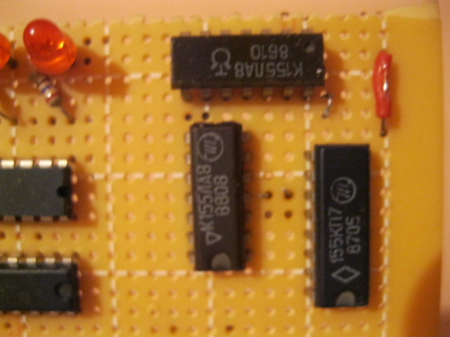
After soldering on the LEDs of my RPN binary calculator, I went on to solder the resistors and the 595 shift-register. Unfortunately, this didn't go as well as soldering the LEDs did! I had a lot of trouble getting the solder to flow and the 595 chip ended up getting really hot and may have been damaged. I definitely used too much solder too. Eventually I had to stop soldering because the tip of my soldering iron wore down. I was using steel wool to clean it between joints and this took out chunks of the tip until there wasn't enough left to properly heat the solder any more. It looks like I will need some practice before I continue!

From what I have heard, a good soldering iron tip should have a copper core and be coated with other metals. The cheap tip I was using seems to be made of only one kind of metal. The only other tip I have been able to find is solid copper. We will see how long I can make it last. One good thing about it is that it is wedge-shaped. Many of the soldering iron tutorials I have read recommend a tip like this but most pictures and videos show people using conical tips. My plan is to see how well this tip works and do some practice before I continue working on my calculator.
In order to practice I got my hands on some Soviet era logic chips. They were available locally for a cheap price and I don't need to worry about destroying them if I get them too hot. Before sacrificing them for the greater good, I decided to hook them up on my breadboard. The two I tried were K155LA8s (К155ЛА8 in Russian). According to
Chip Directory, LA8 is equivalent to a 7401 chip, which has four NAND gates with two inputs each and open collector outputs. This means that the chip should sink current instead of sourcing it when an output is true. Using an LED to test with, I couldn't get the chip to sink any current but when I hooked it up the other way around, it sourced a small amount. This makes me think that the chip is actually equivalent to a 7400. Also, despite what I read on this website:
chipinfo.ru, pin 14 is ground and pin 7 is Vcc, not the other way around. Interesting indeed! The LED I used to test with glowed very dimly, which is to be expected since TTL chips can't source very much current. To remedy this, I hooked the chip up to a transistor labeled "HHE 8051S." (I don't remember exactly what this was salvaged from.) To my surprise, the LED glowed much dimmer when it was driven by the transistor because I had it between the transmitter emitter and ground. Hooked up between the collector and voltage it worked just fine.
 There don't seem to be any local shops that sell good soldering iron tips here. Luckily, though, I was able to buy a few good ones in another city. I was a bit skeptical when the best tips they had only cost a little over a dollar but I brought them home and they work great! I also bought some good 61/39 solder. Using this instead of the cheap 30/70 solder available locally probably helps a lot too. Later I'll see if any of the cheap tips I have work alright with good solder. I don't think I'll risk using cheap solder with the new tip.