Showing posts with label Tiny Calculator. Show all posts

Sunday, March 9, 2025

Tiny Calculator: New Hardware

After figuring out how to build calculator keypads with my new laser cutter, one of the first things I worked on was new hardware with a new keypad for my Tiny Calculator project. The original keypad was made by printing color labels on overhead transparency plastic then cutting those out and gluing them to 3D printed keys. Since the labels were printed in reverse and glued with the ink side down to protect the ink, the glue caused the ink to smudge in some cases. The laser-cut keys, on the other hand, are very crisp and look much better. The only disadvantage is that they come in just one color. Each key is glued down individually to a 3D printed grid, so it would be possible to make some of the keys a third or fourth color as long as there is no more than two colors per key. One thing I want to experiment with in the future is making keys out of two different pieces to get up to four colors on one key.

The original hardware was two circuit boards stacked together with headers that made everything pretty thick. The new version is just one circuit board with everything mounted on top. One way to squeeze everything in such a small space was using magnet wires which take up even less room than the wire-wrap wires on the original. Both sides of the LCD are encased in a 3D printed housing that is glued directly to the battery holder and microcontroller. This makes it impossible to make any changes to the circuit but is worth it to make the body thin. A small header above the LCD allows for programming.

Sunday, December 25, 2022

2023 Project Goals

2022 was another year full of all kinds of fun projects like my 7400 Logic Calculator plan, Interactive 6502 Assembler, and embedded programming on Linux. Although these weren't on my list of 2022 Project Goals list, I did learn a lot from them and make progress towards some of the goals on the list. With 2022 coming to a close, it's time to take stock of my progress from 2022 and set some goals for 2023.

2022 Project Goals

6507 Graphing Calculator - Still working
Despite another year of work on this project, there is still a lot of work left to finish it. The plan to reduce the firmware size to fit into an 8K ROM by using a Forth VM didn't work out as expected. After a little more work, I plan to post about my progress on this from 2022 and how the project will proceed in the future.

This is the one project from the list that is completely finished. It even made it onto Hackaday yesterday! As mentioned in the article, what I learned from this project will be useful for other projects like the PIC32 Calculator below.

Tiny Calculator - No progress
Not much to say here. There just wasn't enough time to get to this one.

PIC32 Calculator - Still working
Although I haven't started on this project formally yet, a lot of my projects from 2022 will help me work on this one. As mentioned in the last project goals post, this shouldn't take as long as other calculators since it won't be necessary to write all the firmware from scratch.


2023 Project Goals
This year, my goal is to finish enough projects to give a presentation at the Hewlett-Packard Handheld Conference (HHC) in fall 2023 like my presentations at HHC 2019 and HHC 2021. This will take a lot of focus which I wasn't able to pull off last year. Hopefully, having a firm date and goal in mind will motivate me. Here is the tentative list of topics:

Although not a calculator, this should be really interesting to present on since the 6502 emulator written in MIPS assembly can be used to emulate 6502 calculator firmware on a PIC32. This is a good one to start with since this project is already finished.

As mentioned above, there is still a lot of work left to do for this though I know exactly how to proceed from here. Barring any unforeseen complications, this should be a straightforward project to finish. This will be one of the main topics of the presentation.

Calculator key comparison
This is another topic where I made a lot of progress in the last year but haven't posted anything yet. My goal is to compare many different ways of making calculator keys using 3D printing, laser cutting, cast plastic and other methods.

PIC32 Calculator
This is the same project from my list last year. This will be the most exciting thing to present on if it's ready in time. 
 

Wednesday, January 5, 2022

2022 Project Goals

Though I haven't made many posts in the past two years, I have been working on projects slowly but surely. As time passes, I realize how important it is to focus on a small number of projects so that some of them eventually get finished. For 2022, I'd like to pick exactly which projects I want to finish. Hopefully this will motivate me and help me focus!


Main projects

6507 Graphing Calculator
This project is still going after 18 months of work. While I haven't made any progress on implementing the new firmware features I mentioned in my last post on this, I have been working a lot on a subproject for verifying the calculator's floating point routines. Like many projects, this took a lot more time than I expected. Hopefully, I'll be done with this subproject soon so I can post about it. I've also been working on a way to make nice plastic keys for the calculator.

PIC32 Robot
This is an idea I've had for a long time for a simple "robot" built using a PIC32 microcontroller. It's a really interesting project that shouldn't take nearly as long as the calculator projects. It will be a good opportunity to get familiar with PIC32s which I want to use for a future calculator project. Hopefully, I can devote a little bit of time to this and still have time to finish or at least make good progress on the 6507 Graphing Calculator this year.


Other projects

Tiny Calculator
Since the 6507 competition began in 2020, I stopped working on this calculator. In the unlikely event that I finish the 6507 calculator this year, I'd like to return to this project and make some major changes. First, the floating point routines need to be redone using proper guard, round, and sticky like I learned how to do for the 6507 calculator. The existing Tiny Calculator firmware doesn't round in a conformant way and instead uses 32 decimal places to try to mitigate the rounding errors. Also, the routines use 9's complement as TI shows in their documentation for BCD subtraction. It became clear after writing most of the firmware that this wasn't the right way to go, but I didn't have the heart to rewrite everything. My plan now is to take as much as I can of the existing firmware and write a library of BCD floating point functions that use 10's complement with 12 decimal places and proper rounding then call those functions from C to rewrite the Tiny Calculator firmware. I'd also like to find a better solution for the keys and case.

PIC32 Calculator
This is another project I have thought about for a long time. This should be much simpler to tackle than my other calculator projects since I won't be writing the firmware from scratch. If I'm able to finish my two main projects this year, this is another one I'd like to start working on.

Monday, June 24, 2019

Tiny Calculator: Keypad

The last few weeks I have spent a lot of time on the keypad for my Tiny Calculator project and the results are a little surprising! After considering a lot of different ways to make caps for the keys, I finally bought a 3D printer, specifically an Ender 3. Before that, I tried using an Xacto knife to cut out a base and a slightly smaller square post from PVC I bought at the craft store. The result was pretty uneven and there didn't seem to be any way to make them all exactly the same size, so I bought the 3D printer the same day. It was easy to put together and has produced great prints from the very first time I tried it!

The first thing I worked on was designing a button cap with a skirt that would keep it from falling out of a grid overlay. It was really easy to do in OpenSCAD. I printed several versions to get the dimensions right and design a hole in the base so it would fit over the posts of the tactile switches. The first version was black and looked really nice. Next, I started on the overlay and experimented with several versions. One that was only 0.5mm thick fell apart when it came off the raft it was printed on, and I eventually settled on 1mm for the thickness. As I experimented with improving it, I added supports that fit over the header pins on the keypad to keep everything straight and holes for longer pins to keep the grid attached. This worked really well to keep the keys straight and attached but the grid was still a little flexible because it was so thin, so I added a 3mm wall around the edge which made the print very rigid.

The buttons themselves were printed with the holes for the posts facing down. The slicer program inserts tiny supports to keep the hole from collapsing while the button is being printed. It took a long time to carve the supports out and the results ended up being a little uneven. Some of the holes were slightly too deep and the entire button post fit in them with no clearance for the button to be pressed. This led some buttons to have a stronger click and some to stick up farther than the others. One thing I tried to make them more even was to print them in rows of five with the hole facing up. The hole depths all turned out extremely uniform but the lip holding them together came out garbled and they easily broke apart since the lip had to basically be printed parallel to the ground with no support. The next time, I turned the row of five on its end, which worked since I had removed the lower skirt edge to make room for the lip holding them together. Printing five of them in a row like this makes the button presses more uniform and the rows straighter.

The design for the keys labels was done in Google Sheets and copy and pasted into Paint. This worked really well! It was way easier to make modifications and keep all the text uniformed and aligned than doing it in Gimp, which I tried a few months ago. Once I had the design, I went to Staples and had them printed on overhead transparencies. Unfortunately, there is no way to print in white on a standard printer, so you couldn't see anything when the labels were put on black buttons. I bought a roll of white plastic and now the labels look exactly how I planned. For the next iteration, I bought a cheap inkjet printer and transparency paper so I can make the labels myself. They are printed in reverse so I can glue the ink side down and avoid smudges from finger presses. I designed and printed a little bracket for cutting out the labels at exactly the right size, but it turned out not to be useful. Super gluing all of the labels on took a couple tries to get right, but I'm very happy with the result! Now that I have the 3D printer, I plan to make similar keypads for some of my other projects.

Test button made from PVC

Different versions of the button cap

Under side of the button caps. The middle one still has supports.

Failed 0.5mm overlay print

1mm overlay print

Overlay with added wall for stability
Failed print of five connected buttons

Successful print of five connected buttons

Bracket for cutting out labels

Keypad labels


Monday, June 10, 2019

Open Projects

After starting on my 7400 Calculator project, I thought about how many projects I have open at the moment. Like a lot of hobbyists, I seem to start more than I finish. Most of these are not abandoned, since I do plan to get back to them someday. I decided to take stock here of how far I am and what is left to do. There are two projects here I have not posted about: 6502 Optimizing Assembler and 6502 Calculator Emulator. There isn't really enough yet to write about, but I might as well mention them since I have been working on them now and then for a while. They would also be good for the github page I want to set up and list when I apply for jobs. My plan is to finish most if not all of these projects before I start on something else. Otherwise the list might keep growing without finishing any of them.


Tiny Calculator
80%
A few weeks ago, I put a lot of work into the interface code, which ended up taking more time and effort than I imagined. Like in my RPN Scientific Calculator, the interface code takes up a lot of space compared to the math routines. So far, I can enter numbers and do addition and subtraction, but I still need to fix the sign of the result. For the rest of the calculations, I need to write a lot of checking code for things like scaling angles before applying trig functions and avoiding inputting negative numbers in logarithm functions. Two weeks ago I made some major progress with the keypad, which I will post about soon.

Posts related to Tiny Calculator


Pocket Calculator
20%
This project kind of stalled because I got busy with other stuff and also because I hit a few hardware problems that I did not solve. The LCD would work when the speed of the SPI clock was set very low and it would continue to work once I turned the speed up to what the LCD is rated for, but if I turned the calculator off, the LCD would not work again until I set the speed back to very slow. The LCD also did not work when I fully closed the case. Eventually, one of the very stiff ethernet wires I was using broke right off. I will need to rewire the LCD with different wire and start over on the emulator I was working on.

Posts related to Pocket Calculator


Programmable RPN Calculator
95%
The last time I worked on this calculator in 2015, I considered it finished other than labels for the keypad. One thing I figured out in the meantime is that the key reading is not entirely reliable since two of the pins on the LPC1114FN28 are open drain, which I did not account for. It also seems that I did not write the key reading code correctly, so there is a chance of shorting pins when you press two keys at once. These probably won't take long to fix, then I will make labels for the keypad, which should be easy now that I have done it for my Tiny Calculator. Another thing that might be helpful is to review the source code and make sure all of my checking code is correct.

Posts related to Programmable RPN Calculator


7400 Logic Calculator
30%
This is my latest project and I have been doing a lot of work on it, so I am still really excited about it. I might try to finish some of the projects that are close to done before I return to this to get them out of the way.


6502 Graphing Calculator
???
In summer 2015, I put this calculator together very quickly to try to get it ready for Makevention that year. Not suprisingly, it did not work at all since I was in such a hurry putting it together. I'm not sure it would be worth it to resurrect this project, but I would like to at least return to it and figure out why it didn't work. One possibility is that the LCD was damaged when I was trying to drive it with an MSP430 since the wires I used had metal connectors that kept shorting to each other. Another thing I noticed when I pulled the board out a few weeks ago was that the EEPROM is not a modern CMOS chip but something older that uses 140mA and has a slow 250ms access time. The latches to drive the LCD are 74LS874s, which I now realize consume way more power than HC chips. There could also be other problems like the CPLD. In any case, it will be fun to try to figure everything out.

Posts related to 6502 Graphing Calculator


6502 Optimizing Assembler
25%
This is a project I started to practice my Python skills and have a concrete project to talk about in job interviews. My plan is to analyze assembly files (not compiled binaries) and make optimizations based on a few simple assumptions. This will should be able to shave a few cycles off of unneeded instructions, which is especially useful when you are using macros. It will also be able to manage zero page much better than just assigning fixed addresses to each function or sacrificing the X register for use as a slow pseudo stack.


6502 Calculator Emulator
40%
This is a 6502 emulator written in JavaScript that will let me test calculator firmware in the browser without having to upload it to a physical calculator. The emulation works at over 50MHz currently and passes Klaus' test suite. The input and screen output work, as well as memory paging like the real calculator will have. Now I have to find a way to speed up screen drawing, since I think this is the source of lag when typing. Then I will need to start writing the firmware for the calculator. Someday I will host it on a website so that other people can help me find bugs.

Wednesday, April 17, 2019

Tiny Calculator: Hardware

Tiny Calculator is business card size.
The hardware for this project is finally done! The first step was getting the LCD running. This time I went with a 128x32 LCD from Newhaven, which is a little pricey at $11. A simple HD44780 compatible LCD like I used for my RPN Scientific Calculator project would give me the same 20x4 character resolution for $3-4, but all the ones I have seen are way too big. Another option would be a small OLED screen, which are very cheap but would drain the CR2032 battery a lot faster.

The LCD has 17 pins with 1.5mm spacing, which is smaller than a breadboard or protoboard but still big enough to solder by hand. The majority of the pins are for capacitors, so I soldered a small adapter board to hold them and route the data pins to a breadboard. This was tedious and more difficult than I imagine when I bought the LCD but the hardware worked on the first try. After I got it running, I epoxied the LCD to the board. Next time, I think I will go with something easier to solder like an OLED screen even if it takes more current.


The datasheet for the LCD has some initialization code, which I could not get to work. A search turned up some working C code from another forum that was easy to get running with GCC for the MSP430. Translating the C code to assembly was a little tricky since some of the variables for initializing the SPI module on the MSP430 are not plain constants as you might expect from looking at the C code. It took some searching in the header files to figure out that what appears to be a constant is actually something cleverly defined to load a configuration value from the MSP430. After I got that working, everything else went smooth. Rather than try to design my own 5x7 font, I reused a character set I found on a German forum, which came in handy on another project I have been working on but haven't posted about yet.

The main board of the calculator is pretty simple. It just holds the microcontroller, CR2032 battery, and some pins for programming. All the wires are 30 gauge wire wrap I got from Mouser, which I really like using. The power lines are thicker gauge, but they are there more for color coding than because I need them to be that thick. 30 gauge copper is supposed to be able to carry more than the few mA I am using without dropping a lot of voltage.

The keypad has 35 keys, which is more than the 25 I was planning on originally. The main reason I did this is because it looked strange to have a square keypad. Also, there were two leftover pins since Xin and Xout can be reused as GPIO if there is no crystal.

 Each key takes up one 3x3 block on the protoboard, which is smaller than the 4x3 spacing of the keypad on my Pocket Calculator project. It turns out, it's not too difficult to bend the legs under the button a little to make them fit the tighter spacing. The LCD and the keypad both plug into the main board with headers.

Since the calculator runs on a battery, it's important to keep the calculator in low power mode as much as possible. This turned out to be surprisingly painless in assembly! Setting up interrupts is very straightforward too. The calculator scans the keypad a few dozen times a second and goes back to sleep if there is no work to be done. Each key has a byte of memory allocated to it to implement a counter for debouncing the keys and showing which keys have been read. My very cheap multimeter shows that the calculator uses a lot less current than the datasheet for the MSP430 and LCD suggest. Hopefully I can borrow better equipment and get a more accurate reading to try to better estimate how long the calculator should run before it needs a new battery.

The interface code is already mostly done and will be the topic of the next post on this project. After that, the only step left is adding the key labels.

Sunday, February 3, 2019

Tiny Calculator: Improved CORDIC


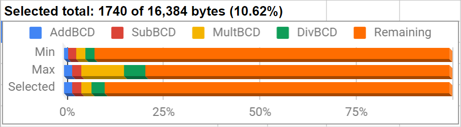
Since my last post I have made a lot of changes to the CORDIC routines I was working on. As you can see in the chart above, the new version fits in less than the 4.1k of the last version even after adding in logarithms. The change came after I found an article about how the HP-35 did CORDIC calculations. Unlike the other descriptions of the method I have used, this version uses an atan table of powers of 10 instead of powers of 2. This lets you shift the arguments by whole decimal places, which is much faster with BCD numbers than powers of 2 . Before, I had wondered if this would be more efficient, but I don't understand the math behind it well enough to modify the routine myself. My implementation of the method the HP-35 uses only takes 90k cycles, compared to the 1.18 million of the last version. The X and Y that the calculation produces, however, cannot be scaled to produce sine and cosine directly. The scale factor depends on the number of rotations, which is easy to precalculate when the angle is halved every iteration, but not possible to know in advance when you use powers of 10 since each iteration requires up to 9 calculations with each affecting the scale factor. As a result, the ratio of X and Y provides the tangent and the HP-35 used identities involving multiplication, division, and square root to generate sine and cosine from tangent. In addition to the 90k cycles for the CORDIC calculation, I would need at least another 140k cycles for these identities. This is 5 times faster than how I was doing it before, although I'm afraid the accuracy would suffer from the added calculations.

The next thing I tried was posting on the HP museum forum, where Thomas Klemm showed me how to do CORDIC calculations in base 10 without resorting to identities. This was a huge help and a much better way to do things than anything I have tried before. The newest routine I have calculates tangent in only 186k cycles and provides sine and cosine without additional calculations! Like in Thomas' version, I tried to make this CORDIC routine more generic so that I can reuse it for inverse trig functions too. Logarithms and powers of e turned out to be much simpler than trig functions using the method described on the same page about the HP-35.

There are still a lot of things to learn about MSP430 assembly. One thing that tripped me up was thinking that RRA automatically shifts a 0 in from the left when rotating when it actually reproduces the leftmost bit instead. Another surprise was that shifting packed BCD by two decimal places is just as fast loading a word from memory, swapping and combining bytes, then writing the result back to memory as it is to just copy bytes directly. I thought the byte copies would be faster, but I was actually able to shave one cycle off by loading and writing words. I rewrote this short section of code five different times trying to save a cycle or two and eventually realized that this is not a useful way to spend my time. This improvement is too tiny to ever be noticeable, and I want to finish this project soon. There are a few other small improvements I have not spent time on since they would provide only a negligible speed up.

The next step is to start working on hardware and the interface code.

Sunday, December 30, 2018

Tiny Calculator: Sine, Cosine, and Tangent

For the trig functions, I started building the same angle table that I used for the CORDIC routines in my RPN Scientific Calculator. Comparing my table to an example calculation I found of how CORDIC works, I noticed that the values are all pi times bigger than the ones in the example. Could I have made the same mistake in my RPN Scientific Calculator? When I get back home from the holidays, I should check to make sure that this does not throw off some of the calculations. Another thing I found out from the same page was that the K value to multiply by after the CORDIC calculation is calculated for a particular number of iterations. In my RPN Scientific Calculator, I included a K value for the maximum number of iterations and truncated it when less precision was used. On second thought, I should have done some testing to make sure truncating the K value to the precision of the argument always yields the best results for a particular level of precision. At the moment I don't plan to redo anything on my older calculators unless something is majorly wrong. It is good, though, to recognize this type of mistake, so I can look out for it in future projects that use CORDIC.

To generate the angle table I used the bc command line calculator. It has a very simple programming language that can run from a script. Interestingly, bc does not seem to do any type of rounding, so the tables I have are unrounded. Maybe I will experiment with a rounded table to see how much of an effect it has. For some of the other tables (including a couple I ended up not needing) I used Python, which has been really helpful. The table itself contains angles descending in size, so I only sto

The first step to implementing the trig functions was replicating the CORDIC calculations in a spreadsheet. This works for about 30 iterations until the numbers become too small for the spreadsheet to handle. Rather than doing bit shift operations like I would on the microcontroller, I multiplied by inverse powers of two, which accomplishes the same goal. When I had that working, I tried generating those multipliers on the MSP430 and multiplying, rather than bit shifts. I thought this might be fairly fast since the multiplier could be left in binary, which makes it quicker to use with the Russian Peasant algorithm, and the amount of zeroes in the multiplier would mean relatively few multiplies altogether. Consider this shortened table of successive inverse powers of two:

Friday, December 14, 2018

Tiny Calculator: Four Functions

The last few weeks I have gone down a little bit of a rabbit hole writing BCD math routines for my Tiny Calculator project. The goal has been to compare different calculation strategies to find which ones are fast but still small enough to fit in the 16k of flash the MSP430 I am using has. Like the addition routines I wrote about in my last post, all of these routines were a lot smaller than I expected. There were also some other surprises about what worked best.

Subtraction
To start with, I based this routine on the setup code for the addition routine, which saves some space. Originally my plan was to make everything modular so that I could substitute pieces of code in depending on what size and speed trade off I wanted, which is why I have separate body and ending options in the table for my addition routine. However, to save space and build one routine off the parts of another, it makes more sense to decide which version to use at the beginning. The only big difference between the two subtraction routines I tried was rolling and unrolling the main loop, with the unrolled version being about 75% faster. It's also about 25% larger but that is only around 50 bytes.

Multiplication
In addition to the straightforward method of repeated additions, I tried the quarter squares and Russian peasant algorithms I learned about doing 6502 BCD multiplication. It was a surprise that using quarter squares was over 10% slower on the MSP430 than the Russian peasant algorithm, whereas it was over 4 times faster on the 6502! Part of the difference may be the speed up I get on the MSP430 by converting each digit of one argument to binary (so it can be halved) only once and saving it, rather than converting it every time like on the 6502. Another major difference is how much slower accessing tables on the MSP430 is compared to register operations. It's interesting how the timing of the architecture can decide which algorithm works the fastest. It's also great that the Russian peasant algorithm doesn't need any tables and is therefore much smaller.

Sunday, November 4, 2018

New project: Tiny Calculator

My Pocket Calculator project has been on the back burner for a few months while I finish my master's thesis. In the mean time, I got interested in doing a much simpler project to make a very small calculator that will hopefully be about 2.5 inches long. This is the size of a 5x5 keypad and the small 128x32 LCD I want to use. Like my first first calculator, it will use a through hole MSP430. The first calculator needed two MSP430s to contain all the firmware, but I think I can fit everything on one chip for this project. It should also be possible to do what I want with the 512 bytes of internal RAM the chip has, so I won't need any external SRAM, and with 25 keys, I also won't need external shift registers. Other than the microcontroller and some capacitors, the only other thing on the board will be a CR2032 battery. The MSP430 needs 2.7v to run at 16MHz, so I plan to run at 8MHz in order to use the battery down to 2.4v. It might be possible to monitor the battery and run at 16MHz as long as the voltage is high enough, but I don't think I will need the extra speed like I did on the last calculator.

One of the main things that got me interested in this project was finding out that the MSP430 has a decimal add instruction that works on packed BCD words. This is really convenient and should be many times faster than doing BCD manually in C like I did for my first calculator. One possibility would be mixing C and assembly to take advantage of features like this, but I am going to try to do the whole thing in assembly to make it as small and fast as possible. Another speed up should come from switching to a 16 byte floating point format. This will let me calculate logarithms and trig functions to the same precision as my first calculator but fit everything in the 512 bytes of internal RAM. Eliminating the bottleneck of transferring data over SPI one bit at a time will probably be the main speed up. For multiplication, I want to try some of the algorithms I tested for the 6502, and for division, I will try out some based on Netwon's Method. For logarithms and trig functions, I'll probably use CORDIC routines again, but I want to see if Taylor polynomials will be much smaller, even if they are slower. With 25 keys, I can fit in just about everything from my first calculator. It should be able to do a little more than an HP-35. The main drawback compared to my first calculator will be less precision with large numbers and less stack space, although neither should be a problem, since there won't be a programmable mode. Also, I plan to keep track of exponents by the byte, rather than the nibble like a did on the first calculator. This will mean losing precision by a factor of 10 in some cases, but it will make aligning numbers during calculation much simpler.