Showing posts with label MSP430. Show all posts

Sunday, March 9, 2025

Tiny Calculator: New Hardware

After figuring out how to build calculator keypads with my new laser cutter, one of the first things I worked on was new hardware with a new keypad for my Tiny Calculator project. The original keypad was made by printing color labels on overhead transparency plastic then cutting those out and gluing them to 3D printed keys. Since the labels were printed in reverse and glued with the ink side down to protect the ink, the glue caused the ink to smudge in some cases. The laser-cut keys, on the other hand, are very crisp and look much better. The only disadvantage is that they come in just one color. Each key is glued down individually to a 3D printed grid, so it would be possible to make some of the keys a third or fourth color as long as there is no more than two colors per key. One thing I want to experiment with in the future is making keys out of two different pieces to get up to four colors on one key.

The original hardware was two circuit boards stacked together with headers that made everything pretty thick. The new version is just one circuit board with everything mounted on top. One way to squeeze everything in such a small space was using magnet wires which take up even less room than the wire-wrap wires on the original. Both sides of the LCD are encased in a 3D printed housing that is glued directly to the battery holder and microcontroller. This makes it impossible to make any changes to the circuit but is worth it to make the body thin. A small header above the LCD allows for programming.

Wednesday, May 8, 2024

MSP430 Development on Linux

For the last few years, I've moved as many of my programming projects as possible from Windows to Linux. This includes PIC32 programming as explained in MIPS Development on Linux. My most recent MSP430 projects like the Electronic Birthday Card, Kitty Salon, and some Christmas tree ornaments for this past Christmas were programmed entirely on Linux. On the other hand, my Tiny Calculator project, which started in 2018, is compiled with IAR Embedded Workbench running on Windows. Since returning to the Tiny Calculator is one of my goals for the coming year, I spent some time improving my MSP430 setup on Linux.

Sunday, February 6, 2022

Electronic Birthday Card

For my friend's birthday, I made her a theater-themed electronic card that sings happy birthday. The outside looks like a theater announcement, and the inside looks like a movie marquee. My girlfriend printed both graphics on a Cricut machine, and they look much better than what I could have come up with myself.

The hardware is pretty simple. The top part, which flips up to show the marquee, is a simple 3D-printed box. My original plan was to use the box as the bottom part to hold the battery and electronics. After waiting six hours for the part to print, I realized it wasn't tall enough to hold the LEDs of the marquee, so the part became the lid instead of the base. For the bottom part, I cut a piece of plexiglass from the hardware store and printed standoffs to attach it to the circuit board. This was my first time working with plexiglass, which turned out to be very easy to crack or break while working with. It's neat to have some experience with it in case another project needs a plexiglass case.

The movie marquee inside has 20 LEDs in total around the edge. They are arranged in five groups of four LEDs with an NPN transistor controlling each group. The groups are interspersed so that each fourth LED is in the same group and shares the same brightness. The blinking pattern rotates clockwise with the brightest LEDs in the front of the pattern so the other LEDs look like they are fading and trailing the brightest one. This looks better than just lighting up one group at a time. The brightness is controlled by simple software PWM running on an MSP430. A timer fires every 1,000 cycles giving 16,000 steps per second since the microcontroller runs at 16MHz. Every time through the loop, the code to adjust the PWM executes then blocks on a while loop waiting for the timer to finish it's 1,000 cycles. This keeps the brightness uniform since a step always takes the same amount of time regardless of how long the PWM code needs.

16,000 steps per second is way more than needed to adjust LED brightness. The extra granularity is useful for controlling the small piezo buzzer that plays happy birthday. The music consists of simple beeps from the speaker, which only takes a few dozen bytes to store and has no problem fitting in the MSP430's flash. The music notes start out as raw frequency values beginning with A at 440Hz. A series of C macros let me calculate how many steps each note needs including a short bit of silence at the end of each one. While I try to avoid overreliance on macros, in this case they really helped list everything in a clear way. Specifying the notes to be played was then very easy:

const unsigned int music_notes[]={

    NOTE(NOTE_C,EIGTH),
    NOTE(NOTE_C,EIGTH),
    NOTE(NOTE_D,QUARTER),
    NOTE(NOTE_C,QUARTER),
    NOTE(NOTE_F,QUARTER),
    NOTE(NOTE_E,HALF),
    ...
    MUSIC_END};

My first try at playing notes in a scale was noticeably off, and two of the notes had the same tone. It took some investigating to figure out that the way I had the timer calculations listed based on the frequency was rounding the highest frequency notes down to a small integer which was between two recognizable notes. This is what lead to the two notes sounding the same since they'd been rounded to the same value. One helpful thing I've started to do since getting interested in assembly language is turning on listing files in the compiler to see what assembly is generated. This showed that the values calculated where way too small, which I double checked with Compiler Explorer. Listing files are a great tool that have helped me solve several bugs like this. After adjusting the calculation macros, the notes sounded just right, and happy birthday played correctly. 

Soldering everything together was a bit of a challenge. The top PCB with the LEDs has the paper with the happy birthday graphic attached to it, so none of the wiring for the LEDs could go completely through the board since they would have to penetrate the paper too. Instead, all of the wires and resistors are soldered flat on the back. This is a technique that might come in handy someday for something else.


The MSP430, transistors, and buzzer are on a small separate PCB sandwiched between the top PCB and a piece of plexiglass. The battery pack and on/off switch are attached to the plexiglass with hot glue. Although I've never been very impressed with the durability of hot glue, whatever type I got from the craft store this time is absurdly strong and was more than good enough for this project.

Wednesday, January 5, 2022

2022 Project Goals

Though I haven't made many posts in the past two years, I have been working on projects slowly but surely. As time passes, I realize how important it is to focus on a small number of projects so that some of them eventually get finished. For 2022, I'd like to pick exactly which projects I want to finish. Hopefully this will motivate me and help me focus!


Main projects

6507 Graphing Calculator
This project is still going after 18 months of work. While I haven't made any progress on implementing the new firmware features I mentioned in my last post on this, I have been working a lot on a subproject for verifying the calculator's floating point routines. Like many projects, this took a lot more time than I expected. Hopefully, I'll be done with this subproject soon so I can post about it. I've also been working on a way to make nice plastic keys for the calculator.

PIC32 Robot
This is an idea I've had for a long time for a simple "robot" built using a PIC32 microcontroller. It's a really interesting project that shouldn't take nearly as long as the calculator projects. It will be a good opportunity to get familiar with PIC32s which I want to use for a future calculator project. Hopefully, I can devote a little bit of time to this and still have time to finish or at least make good progress on the 6507 Graphing Calculator this year.


Other projects

Tiny Calculator
Since the 6507 competition began in 2020, I stopped working on this calculator. In the unlikely event that I finish the 6507 calculator this year, I'd like to return to this project and make some major changes. First, the floating point routines need to be redone using proper guard, round, and sticky like I learned how to do for the 6507 calculator. The existing Tiny Calculator firmware doesn't round in a conformant way and instead uses 32 decimal places to try to mitigate the rounding errors. Also, the routines use 9's complement as TI shows in their documentation for BCD subtraction. It became clear after writing most of the firmware that this wasn't the right way to go, but I didn't have the heart to rewrite everything. My plan now is to take as much as I can of the existing firmware and write a library of BCD floating point functions that use 10's complement with 12 decimal places and proper rounding then call those functions from C to rewrite the Tiny Calculator firmware. I'd also like to find a better solution for the keys and case.

PIC32 Calculator
This is another project I have thought about for a long time. This should be much simpler to tackle than my other calculator projects since I won't be writing the firmware from scratch. If I'm able to finish my two main projects this year, this is another one I'd like to start working on.

Monday, January 3, 2022

TI-86 Battery Discharger

In 2015, I got an ESP8266 with the hopes of using it to connect a graphing calculator to the internet. The plan was to swap the four 1.5v AAA batteries in a TI-86 for two 3.6v 10440 batteries and use the space freed up in the battery compartment to house the ESP8266. The TI-86 would have acted as a terminal to more powerful mathematical software like Mathematica or Matlab running on my computer. My last post mentioning this project was about Makevention 2015 and explained that there were power supply problems running the ESP8266 on a breadboard. Since then, this project has been on the back burner.

While I haven't done anything with the ESP8266 since then, I did put batteries in the TI-86 this past year so it would be ready to use if I ever wanted it. When I turned it on, the screen was solid black. This happens sometimes with new batteries when the contrast is set too high after being increased over and over as the last set of batteries decreases in voltage. This time, adjusting the contrast down didn't show any noticeable change. After a few minutes of letting the calculator run, the contrast decreased gradually until the text on the screen was visible. This was really puzzling behavior.

Searching the internet didn't turn up much for calculators that malfunction with a dark screen. While trying to troubleshoot the problem myself, I checked the voltage of the batteries with my multimeter. In all of my calculators, I have Lithium AAAs since they don't leak and damage the calculator the way alkalines can. The voltage of the AAAs in the TI-86 was around 1.8v, far above the 1.5v nominal voltage of a AAA and the 1.6v of new alkaline AAAs I've measured. After letting the calculator run a while until the text on the screen became visible, I measured the battery voltage again and it was over 1.6v. It seems the voltage drops as the calculator runs which eventually lowers the contrast, so I decided to build a circuit to discharge the batteries down to the optimal point for the contrast.

The discharger I built uses an MSP430 to switch an NPN transistor that bleeds the batteries for one second at a time through eight parallel 1/4W resistors. After each one second discharge, the MSP430 takes an ADC voltage reading from a resistor divider that lowers the battery voltage down to the range the MSP430 can safely measure. The MSP430 then displays the ADC voltage read, the calculated voltage of the batteries, and run time on a very small OLED. Part of the justification (and fun) for this project was learning how to drive the OLED since I'd like to use one for a calculator screen someday. The whole discharge process repeats until the battery voltage hits 1.55v. In my case, it took 42 seconds to hit the target voltage. 

After the batteries discharged to 1.55v, I put them in the TI-86 and the contrast was perfect! This was very satisfying. However, the next morning when I woke up and turned the calculator on, the contrast was back to solid black since the battery voltage had floated back up to over 1.7v overnight. Apparently, this is a normal part of battery chemistry. For the discharger to work, I would need to figure out how far down below 1.55v to discharge the batteries so that they wouldn't rise over 1.6v overnight. Rather than spending multiple days testing battery discharge and recovery cycles, I soldered a piece of protoboard to replace one of the four batteries and lower the average total voltage:


This lowered the contrast to the right level. Ultimately, the battery discharger was a failure though I had fun building something new with an MSP430 and learned how to drive an OLED display. After a year, the contrast still looks great.

Sunday, January 2, 2022

Linux for Embedded Development

A little over a year ago, I bought a new Casio FX-9750GIII graphing calculator. It really appealed to me for several reasons so I decided to buy one even though my days of collecting calculators are mostly over. One of the main things I like is that it comes with Python which has become one of my favorite programming languages. Another interesting thing is that the processor speed was doubled to 59MHz over the preceding FX-9750GII making it as fast as the FX-9860GII and the FX-CG50. Amazingly, there is a port of Xcas for it, so you can run the same Computer Algebra System (CAS) used in the HP PrimeTI-89, and TI-Nspire. The styling of this one has changed back to the standard rectangular design which is much better than the awkward and ugly rounded design Casio used for some of the preceding models. All of this is very impressive and it only costs $39! Best of all, it can run programs written in C and assembly like previous Casio models. Other modern calculators like the HP PrimeTI-Nspire, and TI-84+ CE don't allow native code execution which is why I've stayed away from them. The catch with the FX-9750GIII is that the GCC toolchain put together by the community only runs on Linux. It took quite a bit of work getting the toolchain installed on Ubuntu in a virtual machine since I didn't have much experience with Linux. A few months ago, I moved everything over to an old server that someone donated. Below are some things I've learned while doing more and more of my embedded projects on Ubuntu.

Virtual Machine
At first, I installed Ubuntu Server on VirtualBox so I could use the GCC toolchain for the FX-9750GIII. It took quite a while to install and then some more work to get things like networking and a shared folder with the host to work. The GCC toolchain turned out to be very problematic to install which was not entirely due to my lack of experience with Linux. Thankfully, the maintainer of the toolchain put in a lot of work helping me get it working on the Planet Casio forum. One of the first problems was trying to get the scripts working without understanding how the various types of shells work in Linux which is very different from the Windows command prompt I'm used to using. There is a package called GiteaPC that the maintainers put together that is supposed to install everything, but this didn't work for me at first either. Other problems were beyond my control such as not being able to update CMake to the version the toolchain requires. For this, I had to update Ubtuntu from 20.04 LTS to 21.04 which does not have long term support. CMake also had problems finding the PATH variables. Eventually, I did get the toolchain running, though it failed when trying to install it again sometime later since the maintainers had changed the toolchain's structure so it no longer built correctly. In the end, I did get GiteaPC working, again with the help of the maintainers, though I have to say the weeks-long process of just getting to Hello, World was pretty awful. All of this led me to reinstalling Ubuntu several times on VirtualBox.

Thursday, December 30, 2021

Kitty Salon

For Christmas this year, my girlfriend and I made a talking toy cat for her nephew. It was a fun opportunity to build something together and practice some fabrication skills that are useful for calculator projects.

The idea for this project came from her nephew pretending to be a cat and calling himself "Kitty Salon." The toy version of Kitty Salon has five recorded messages saying things like "Meow! Meow!" and "Rise and shine!" A button on the bottom plays one of the messages every time it's pressed, cycling through all five. Two LEDs for eyes glow to show that the cat is on and fade on and off while the cat is talking.

Body
The first step to building the cat was sculpting a model out of clay. The innermost part of the model is a small box made out of foamcore which is large enough to hold all the electronics. The first try at making the cat out of clay from the craft store failed. The box the clay came in said that it dries when exposed to water. In our case, the model cracked in several places after drying and the feet fell off. The second try used Sculpey which doesn't require water to set and has the added benefit of working well with silicone rubber molds. You can see in the picture above that the back end of the cat is a little square and fat since the Sculpey is molded around the box for the electronics.

Sunday, December 8, 2019

Optimized MSP430 Assembly in Mecrisp Forth


A few years ago, I got interested in Forth due to its connection to RPN calculators but lost interest because of the huge hit to performance a stack-based system takes on an architecture like 6502. Recently, my interest was piqued again during a conversation in the #Forth IRC channel on FreeNode about Mecrisp-Across, which uses an ARM-based microcontroller board to produce optimized assembly for the MSP430. Because the compiler tries to keep values in registers instead of the stack, it has the potential to reclaim some of the performance lost in most Forths. Some of these optimizations might be useful for a 6502-based Forth, so I tried to understand how optimizations in Mecrisp work.

The first step was getting Mecrisp running on a PC. The author provides versions that are compiled for ARM with Linux system calls, so you can use QEMU for emulation under Linux. Getting this working on Windows was a real challenge. One Debian image I tried emulating with QEMU crashed the emulator outright. Another image booted into Linux but refused to install QEMU complaining about needing the Linux CD in the drive before it would install any packages. Getting Ubuntu working on VirtualBox under Windows 10 and installing QEMU on it wasn't too tough, but the Mecrisp image wouldn't run until I got the right type of QEMU (there are several). The right combination was VirtualBox, an Ubuntu image from OSboxes, and QEMU-user-static.

Wednesday, April 17, 2019

Tiny Calculator: Hardware

Tiny Calculator is business card size.
The hardware for this project is finally done! The first step was getting the LCD running. This time I went with a 128x32 LCD from Newhaven, which is a little pricey at $11. A simple HD44780 compatible LCD like I used for my RPN Scientific Calculator project would give me the same 20x4 character resolution for $3-4, but all the ones I have seen are way too big. Another option would be a small OLED screen, which are very cheap but would drain the CR2032 battery a lot faster.

The LCD has 17 pins with 1.5mm spacing, which is smaller than a breadboard or protoboard but still big enough to solder by hand. The majority of the pins are for capacitors, so I soldered a small adapter board to hold them and route the data pins to a breadboard. This was tedious and more difficult than I imagine when I bought the LCD but the hardware worked on the first try. After I got it running, I epoxied the LCD to the board. Next time, I think I will go with something easier to solder like an OLED screen even if it takes more current.


The datasheet for the LCD has some initialization code, which I could not get to work. A search turned up some working C code from another forum that was easy to get running with GCC for the MSP430. Translating the C code to assembly was a little tricky since some of the variables for initializing the SPI module on the MSP430 are not plain constants as you might expect from looking at the C code. It took some searching in the header files to figure out that what appears to be a constant is actually something cleverly defined to load a configuration value from the MSP430. After I got that working, everything else went smooth. Rather than try to design my own 5x7 font, I reused a character set I found on a German forum, which came in handy on another project I have been working on but haven't posted about yet.

The main board of the calculator is pretty simple. It just holds the microcontroller, CR2032 battery, and some pins for programming. All the wires are 30 gauge wire wrap I got from Mouser, which I really like using. The power lines are thicker gauge, but they are there more for color coding than because I need them to be that thick. 30 gauge copper is supposed to be able to carry more than the few mA I am using without dropping a lot of voltage.

The keypad has 35 keys, which is more than the 25 I was planning on originally. The main reason I did this is because it looked strange to have a square keypad. Also, there were two leftover pins since Xin and Xout can be reused as GPIO if there is no crystal.

 Each key takes up one 3x3 block on the protoboard, which is smaller than the 4x3 spacing of the keypad on my Pocket Calculator project. It turns out, it's not too difficult to bend the legs under the button a little to make them fit the tighter spacing. The LCD and the keypad both plug into the main board with headers.

Since the calculator runs on a battery, it's important to keep the calculator in low power mode as much as possible. This turned out to be surprisingly painless in assembly! Setting up interrupts is very straightforward too. The calculator scans the keypad a few dozen times a second and goes back to sleep if there is no work to be done. Each key has a byte of memory allocated to it to implement a counter for debouncing the keys and showing which keys have been read. My very cheap multimeter shows that the calculator uses a lot less current than the datasheet for the MSP430 and LCD suggest. Hopefully I can borrow better equipment and get a more accurate reading to try to better estimate how long the calculator should run before it needs a new battery.

The interface code is already mostly done and will be the topic of the next post on this project. After that, the only step left is adding the key labels.

Sunday, February 3, 2019

Tiny Calculator: Improved CORDIC


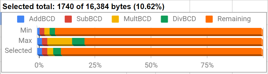
Since my last post I have made a lot of changes to the CORDIC routines I was working on. As you can see in the chart above, the new version fits in less than the 4.1k of the last version even after adding in logarithms. The change came after I found an article about how the HP-35 did CORDIC calculations. Unlike the other descriptions of the method I have used, this version uses an atan table of powers of 10 instead of powers of 2. This lets you shift the arguments by whole decimal places, which is much faster with BCD numbers than powers of 2 . Before, I had wondered if this would be more efficient, but I don't understand the math behind it well enough to modify the routine myself. My implementation of the method the HP-35 uses only takes 90k cycles, compared to the 1.18 million of the last version. The X and Y that the calculation produces, however, cannot be scaled to produce sine and cosine directly. The scale factor depends on the number of rotations, which is easy to precalculate when the angle is halved every iteration, but not possible to know in advance when you use powers of 10 since each iteration requires up to 9 calculations with each affecting the scale factor. As a result, the ratio of X and Y provides the tangent and the HP-35 used identities involving multiplication, division, and square root to generate sine and cosine from tangent. In addition to the 90k cycles for the CORDIC calculation, I would need at least another 140k cycles for these identities. This is 5 times faster than how I was doing it before, although I'm afraid the accuracy would suffer from the added calculations.

The next thing I tried was posting on the HP museum forum, where Thomas Klemm showed me how to do CORDIC calculations in base 10 without resorting to identities. This was a huge help and a much better way to do things than anything I have tried before. The newest routine I have calculates tangent in only 186k cycles and provides sine and cosine without additional calculations! Like in Thomas' version, I tried to make this CORDIC routine more generic so that I can reuse it for inverse trig functions too. Logarithms and powers of e turned out to be much simpler than trig functions using the method described on the same page about the HP-35.

There are still a lot of things to learn about MSP430 assembly. One thing that tripped me up was thinking that RRA automatically shifts a 0 in from the left when rotating when it actually reproduces the leftmost bit instead. Another surprise was that shifting packed BCD by two decimal places is just as fast loading a word from memory, swapping and combining bytes, then writing the result back to memory as it is to just copy bytes directly. I thought the byte copies would be faster, but I was actually able to shave one cycle off by loading and writing words. I rewrote this short section of code five different times trying to save a cycle or two and eventually realized that this is not a useful way to spend my time. This improvement is too tiny to ever be noticeable, and I want to finish this project soon. There are a few other small improvements I have not spent time on since they would provide only a negligible speed up.

The next step is to start working on hardware and the interface code.

Sunday, December 30, 2018

Tiny Calculator: Sine, Cosine, and Tangent

For the trig functions, I started building the same angle table that I used for the CORDIC routines in my RPN Scientific Calculator. Comparing my table to an example calculation I found of how CORDIC works, I noticed that the values are all pi times bigger than the ones in the example. Could I have made the same mistake in my RPN Scientific Calculator? When I get back home from the holidays, I should check to make sure that this does not throw off some of the calculations. Another thing I found out from the same page was that the K value to multiply by after the CORDIC calculation is calculated for a particular number of iterations. In my RPN Scientific Calculator, I included a K value for the maximum number of iterations and truncated it when less precision was used. On second thought, I should have done some testing to make sure truncating the K value to the precision of the argument always yields the best results for a particular level of precision. At the moment I don't plan to redo anything on my older calculators unless something is majorly wrong. It is good, though, to recognize this type of mistake, so I can look out for it in future projects that use CORDIC.

To generate the angle table I used the bc command line calculator. It has a very simple programming language that can run from a script. Interestingly, bc does not seem to do any type of rounding, so the tables I have are unrounded. Maybe I will experiment with a rounded table to see how much of an effect it has. For some of the other tables (including a couple I ended up not needing) I used Python, which has been really helpful. The table itself contains angles descending in size, so I only sto

The first step to implementing the trig functions was replicating the CORDIC calculations in a spreadsheet. This works for about 30 iterations until the numbers become too small for the spreadsheet to handle. Rather than doing bit shift operations like I would on the microcontroller, I multiplied by inverse powers of two, which accomplishes the same goal. When I had that working, I tried generating those multipliers on the MSP430 and multiplying, rather than bit shifts. I thought this might be fairly fast since the multiplier could be left in binary, which makes it quicker to use with the Russian Peasant algorithm, and the amount of zeroes in the multiplier would mean relatively few multiplies altogether. Consider this shortened table of successive inverse powers of two:

Friday, December 14, 2018

Tiny Calculator: Four Functions

The last few weeks I have gone down a little bit of a rabbit hole writing BCD math routines for my Tiny Calculator project. The goal has been to compare different calculation strategies to find which ones are fast but still small enough to fit in the 16k of flash the MSP430 I am using has. Like the addition routines I wrote about in my last post, all of these routines were a lot smaller than I expected. There were also some other surprises about what worked best.

Subtraction
To start with, I based this routine on the setup code for the addition routine, which saves some space. Originally my plan was to make everything modular so that I could substitute pieces of code in depending on what size and speed trade off I wanted, which is why I have separate body and ending options in the table for my addition routine. However, to save space and build one routine off the parts of another, it makes more sense to decide which version to use at the beginning. The only big difference between the two subtraction routines I tried was rolling and unrolling the main loop, with the unrolled version being about 75% faster. It's also about 25% larger but that is only around 50 bytes.

Multiplication
In addition to the straightforward method of repeated additions, I tried the quarter squares and Russian peasant algorithms I learned about doing 6502 BCD multiplication. It was a surprise that using quarter squares was over 10% slower on the MSP430 than the Russian peasant algorithm, whereas it was over 4 times faster on the 6502! Part of the difference may be the speed up I get on the MSP430 by converting each digit of one argument to binary (so it can be halved) only once and saving it, rather than converting it every time like on the 6502. Another major difference is how much slower accessing tables on the MSP430 is compared to register operations. It's interesting how the timing of the architecture can decide which algorithm works the fastest. It's also great that the Russian peasant algorithm doesn't need any tables and is therefore much smaller.

Sunday, November 4, 2018

New project: Tiny Calculator

My Pocket Calculator project has been on the back burner for a few months while I finish my master's thesis. In the mean time, I got interested in doing a much simpler project to make a very small calculator that will hopefully be about 2.5 inches long. This is the size of a 5x5 keypad and the small 128x32 LCD I want to use. Like my first first calculator, it will use a through hole MSP430. The first calculator needed two MSP430s to contain all the firmware, but I think I can fit everything on one chip for this project. It should also be possible to do what I want with the 512 bytes of internal RAM the chip has, so I won't need any external SRAM, and with 25 keys, I also won't need external shift registers. Other than the microcontroller and some capacitors, the only other thing on the board will be a CR2032 battery. The MSP430 needs 2.7v to run at 16MHz, so I plan to run at 8MHz in order to use the battery down to 2.4v. It might be possible to monitor the battery and run at 16MHz as long as the voltage is high enough, but I don't think I will need the extra speed like I did on the last calculator.

One of the main things that got me interested in this project was finding out that the MSP430 has a decimal add instruction that works on packed BCD words. This is really convenient and should be many times faster than doing BCD manually in C like I did for my first calculator. One possibility would be mixing C and assembly to take advantage of features like this, but I am going to try to do the whole thing in assembly to make it as small and fast as possible. Another speed up should come from switching to a 16 byte floating point format. This will let me calculate logarithms and trig functions to the same precision as my first calculator but fit everything in the 512 bytes of internal RAM. Eliminating the bottleneck of transferring data over SPI one bit at a time will probably be the main speed up. For multiplication, I want to try some of the algorithms I tested for the 6502, and for division, I will try out some based on Netwon's Method. For logarithms and trig functions, I'll probably use CORDIC routines again, but I want to see if Taylor polynomials will be much smaller, even if they are slower. With 25 keys, I can fit in just about everything from my first calculator. It should be able to do a little more than an HP-35. The main drawback compared to my first calculator will be less precision with large numbers and less stack space, although neither should be a problem, since there won't be a programmable mode. Also, I plan to keep track of exponents by the byte, rather than the nibble like a did on the first calculator. This will mean losing precision by a factor of 10 in some cases, but it will make aligning numbers during calculation much simpler.

Sunday, June 24, 2018

Calculator Processors

Most of the microcontrollers and processors I have looked into using have been for my calculator projects. That's one of the main reasons I did my microcontroller comparison a few years ago. Recently, I have gotten interested in other chips I could use for calculator projects, in addition to the 6502, 6800 family, and 8051 chips I was interested in before.

The main two criteria I have are an external memory bus and through-hole package. Right away, this eliminates most modern microcontrollers, since almost all of them with an external memory bus are SMD only. In theory, I could use a chip without an external bus if it had a few hundred KB of RAM for data and a few hundred more KB of RAM or flash for program space, but I haven't found that in a through-hole package. Another point is that I would like the ability to load programs from an SD card, which is impractical if I need to have the chip reflash itself every time I load a program. Through-hole parts are more convenient to solder, and I would like to do a few more projects with them before I try to start making surface mount boards.

Modern microcontrollers
  • AVR - None of the ATmega series has an external bus. Some of the ATxmega series do, but they don't come in through-hole packages.
  • PIC - For a through-hole part, the PIC32 series is very impressive at 50mhz with 64KB RAM and 256KB of flash, but even this is not enough for what I am planning. The chip requires a separate programmer, and the compiler offers limited optimizations unless you pay, which is absurd in 2018 compared to its competition. It does have something called PMP, which offers a sort of data bus, but it can only address 12 bits, since the DIP part only has 28 pins. 
  • MSP430 - This chip worked well for my RPN Scientific Calculator, but it also lacks an external bus.
  • Propeller - This is an interesting chip but like the others, it lacks an external bus and does not have enough flash or RAM. The one interesting possibility is doing several calculations in parallel, although I don't know how I would use that for a calculator.
  • Zilog - They have some nice chips, including some processors with external buses, but I would like to use something different than what the TI-83 and similar models use.
  • LPC1114 - I really like this chip, and I am using it in my Pocket Calculator, but it also lacks an external bus, and it seems that it is no longer manufactured.

Tuesday, August 11, 2015

New Project: 6502 Graphing Calculator

One of the last things I want to make progress on before Makevention in a few weeks is a graphing calculator I have been planning for quite a while. It will use a 65C02 and is the main reason I started on my 6502 Virtual Trainer last year. Most models of Texas Instrument's graphing calculators use a Z80, which was a competitor to the 6502 in the past. Those models have a 6 or 15MHz clock. The Z80 needs roughly three times more cycles than a 6502 to accomplish the same task, so running this calculator at 5MHz should be as fast as one of those calculators at 15MHz. At the maximum speed of 14MHz, it should be nearly three times as fast. Interestingly, Hewlett Packard did produce several non-graphing calculators like the HP-35S, which used a 8502 chip based on the 6502. Later models of TI calculators used the Motorola 68000 and the latest use ARM processors. These will certainly outperform anything I could make with a 6502. My hope is to make something in power between the Z80 and 68000 series with a few added features.

So far I have finished most of the decoding logic in the ATF1508 CPLD I have been working on. It has 57
IO pins and I have managed to use them all without finishing all the functionality I need. My plan is to use a 512KB SRAM chip with the first 2KB of address space always mapped to the first 2KB of the SRAM. The next two 30KB chunks of address space will point to two windows in the SRAM controlled by the CPLD. This will let me copy large chunks of data between two parts of the SRAM without changing the window between copies. Hopefully 30KB is enough for any single program the calculator will need to run. The last 2KB will be the EEPROM. This is hopefully enough space for a small bootloader that will copy firmware from an SD card and into the SRAM banks. The peripherals like the keyboard and LCD are mapped into the last few bytes of the first 2KB of SRAM.

For the LCD I found a fairly cheap 3.2 inch 320x240 color LCD on eBay. It is the perfect size for a calculator like this. It was also easy to get working with an MSP430 and some shift registers. The only downside is that I did not get an SPI version and I do not have enough CPLD pins to drive the 16 bit data port. The good news is that the LCD seems to expect 3v signals, so I will need some shift registers for level shifting anyway, which frees up a lot of pins. I don't think I will be able to finish very much more of this project for Makevention but I would like to get it drawing to the LCD from a program stored on an EEPROM by then. If I do have extra time, I will work on getting it to read a keypad.

Thursday, June 25, 2015

Summer Hackathon: Update

During the past few weeks I have had a lot of time to work on the projects I planned for my Summer Hackathon. So far I haven't made as much progress as I hoped, mostly because two of them took a lot more time to get going than I expected. Here is my what I have done so far on the ones I have worked on.

EEPROM Computer
Basing a computer architecture on precomputed lookup tables seemed like a an interesting idea when I started working on an assembler program for a 4-bit EEPROM-based computer. On IRC I explained what I was intending and the creator of the CADET computer showed me what he had accomplished. It is more or less the same thing I wanted to build, so I decided to stop work on this project for the time being. After discussing the idea with a friend at our hackerspace, I decided that it would only be worth continuing this project if I expanded it to a 16 or 32-bit architecture.

Brainfuck Microcontroller
For this project I have only hooked up four 74ALS193 counters since the last update. These will be the address counters for the program memory. My plan is to build the computer in small parts on a breadboard and transfer them to protoboard when I finish each piece. Rather than lay everything out on a a large board, I started soldering 8x12cm boards that will stack with double row headers. This way I will have plenty of pins to transfer signals between boards. I also plan to put LEDs on the topmost board to show signals like the address, jump buffer, op code, data pointer, and control signals.

ESP8266
A guy at our hackerspace was having trouble getting his ESP8266 going, so I set mine up to figure
out how to do it. Luckily for me, mine worked fairly well on the first try. The 03 variant I bought last year looked especially good since it is a little smaller than the others I looked at, and has several GPIOs, which I will need for one of the projects I have planned. One inconvenient thing is the 2mm pitch of the pins, which is slightly smaller than the 2.54mm, or 0.1'', pitch of a breadboard, but I soldered a small adapter. The firmware behavior is a little different than what some of the tutorials say to expect, but I was able to get a list of wireless networks at my house and connect to the WiFi at our hackerspace.
The LED of my friend's ESP8266 only lit dimly on my breadboard, as the voltage dropped down as low as 2.3v when run through the 3.3v LM1117 regulator I was running my repurposed 5v supply through. We haven't been able to figure out why this happens yet. For my chip the voltage also sank to about 3v, but it was still enough to keep the chip working. The supply itself seems to be good, as it delivers 5.18v, so I think the problem is with the regulator. When I tested the supply without the regulator on a breadboard with the 74ALS193 counters for the Brainfuck microcontroller, one side of the breadboard was down to 4.8v while the supply was still at 5.18v. Moving the jumper wires on the power rails around brought everything back to 5.18v

Wireless Breadboard
This project was especially exciting to me because it can be used to debug several of the other projects. To begin with I cut one of my 8x12cm protoboards in half and soldered single-row female headers to them, so a breadboard with male headers soldered on could be plugged into it. Unfortunately, I miscalculated the width of the breadboard and soldered the female headers on too wide apart. My local shop has been out of headers lately, so I tried to desolder the headers and broke a row of them in half in the process. So far I would consider this project a failure.

ATF1508 CPLD
This is an essential part of the 6502-based calculator I am hoping to build soon. Unfortunately, it has been my main source of headaches over the past few weeks. First of all, I tried to program the chip with an MSP430 generating JTAG signals from an svf file but this failed. After some searching, I found out that the JTAG standard is not really "standard" at all, and chips from different manufacturers handle the standard differently. Next, I tried generating a pcf file from the svf file, because it contains the actual states of every pin on every clock cycle. Although this worked and I could program the chip, the programming steps were ridiculously complicated. After using Atmel's WinCUPL program (which itself is rather unpleasant to use) to generate a JEDEC file, I convert it to an svf file with the Atmel ISP program. The problem with this is that the program offers a couple of nonsense error messages and just crashes if the FTDI cable I use to communicate with the MSP430 is still plugged in when I start the program or click the button to generate the svf file. Next, I have to switch to a virtual machine to generate the pcf file, since Atmel's SVF2PCF utility is 16-bit only.
After generating this, I have to replug my FTDI cable into USB and start a program I wrote myself to stream the PCF bytes to the MSP430. In an effort to streamline the process, I tried using Altera's SVF2PCF utility to generate the pcf file, since it is 32-bit, but unbelievably it leaves out all delay statements necessary for programming. When I tried transferring this file, the CPLD stopped responding and is now essentially bricked. For some incomprehensible reason the pins necessary for programming can be reassigned to other purposes, rendering the chip unprogrammable. At $14 apiece, this was an expensive error to make.
When my troubles with this chip started, I ordered a Byteblaster JTAG programmer, as the Atmel datasheets list this as a possibility for programming the chip. When it arrived, I quickly found out that the USB Byteblaster I had ordered has nothing at all to do with the Byteblaster cable that Atmel ISP can use. The open source driver I tried for the programmer caused my Windows 7 computer to crash with the blue sreen. Next, I ordered a USB to parallel converter cable, since the schematic for the Byteblaster is just a 74HC244 chip connected to the parallel port. So far I have not tried programming with this chip and may go back to programming with the pcf files generated by Atmel's 16-bit SVF2PCF utility.

Improved 6502 Virtual Trainer
In my post about GCC for the STM32F429 I explained how difficult it had been to get a GCC toolchain running. While I did get the toolchain to work in the end, I was unable to make any of the USB-to-serial examples work. This is very attractive for this project because I could use the chip as a Virtual Com Port and wouldn't need an FT232 chip or USB-to-serial cable. Many examples used the STM32CubeMx program from ST to generate the base code. None of the generated projects, however, can be opened with Eclipse, This is especially disappointing considering that the page for the utility lists GCC as a supported toolchain (although it is not actually in the list of toolchains in the project generator!) and provides an Eclipse plugin form of the utility. As I stated before, developing for STM32 with free tools has been a real pain! I tried the OpenSTM32 IDE, which is based on Eclipse and the libopencm3 library. This was able to compile a USB project generated by STM32CubeMx, but not without a good bit of fiddling with the files generated.
Next I soldered a small board for the 6502 that fits on the STM32 board. The pins of each port are not grouped together on the chip or on the headers on the board, but 8 of the 16 pins of port A are grouped together so I connected the 6502 data bus to them. Pins PA1 and PA2 only rose to 0.6v when driven high, which seems to be due to them being connected to some of the peripherals on the board. I connected PB1 and PB2 in those pins' place, so reading or writing the data bus means combining data from two different ports, but it does work. So far I have the chip working in single-cycle mode with the same software I made for the first trainer. My plan is to leave this software unchanged so it will work with either board.

Makevention
Our hackerspace is sponsoring a convention for makers in August and I would like to show some of my calculator projects there, so for the next two months I plan to focus mostly on the Improved 6502 Trainer and ATF1508 CPLD. These will both be necessary for the next calculator I want to build.

Sunday, March 1, 2015

RPN Scientific Calculator: Keypad

The last part of my RPN Scientific Calculator is the keypad. Before, I had considered trying to make individual key labels somehow. If I could print them on something like the material credit cards are made out of, I could cut them up and glue them to the keys. In the end, gluing on 42 labels without getting glue inside any of the buttons sounded daunting. Instead, I was able to make one out of stamp rubber on the laser cutter at our hackerspace. It turned out really well and I was able to paint the buttons different colors. At this point, there is nothing left to add, so I consider the project totally finished.

Saturday, February 21, 2015

EEPROM Programmer

For a couple of projects I want to work on in the next few months I will need to use EEPROMs. Another member at our hackerspace I have been working with on the BrainFuck microcontroller gave me a few EEPROMs and UV-erasable EPROMs. Like I posted before, I was able to program some of the EEPROMs with an MSP430 on a breadboard and now I have it soldered onto protoboard.


The UART is handled by an FT232R chip that I deadbugged. It gave me a lot of problems when I first soldered 24 gauge Ethernet wire to the pins. At first I tried to tin the pins and this led to several shorts. Because the chip was superglued to the board, there was no way to get at them to fix it. Pure acetone paint remover did not take the superglue off and neither did soaking the board in fingernail polish remover for several hours. The glue got gummy but would not come off, so I left the chip where it was and soldered female headers next to it. Then I soldered another FT232R onto a small piece of protoboard with male headers so I could plug it in to replace the other chip. You can see it on the left side of the picture with the red wirewrap wire. The old chip is partly visible just underneath. The first time I tried I accidentally shorted some of the pins together when I was soldering them, so I bent them vertically to make it easier to get at them. When I bent one down to make more room, it broke off. Unfortunately this was the Vcc pin which I couldn't do without so I had to start over with a third chip. Once I got everything soldered, it worked fine.

The local electronics store did not have any USB B connectors so I had to use a dual USB A connector. The MSP430 is running off the 3.3v provided by the FT232R, so I was afraid of programming it at 3.6v with a LaunchPad since 0.3v above Vcc is the absolute maximum rating in the datasheet. That's why I have the two programming lines running through diodes on the little protoboard above the MSP430. The third "bandaid" piece of protoboard holds two transistors for level shifting. Controlling the EEPROM WE and OE lines with the MSP430 worked fine but it turns out that TTL chips can source voltage from their inputs which would damage the MSP430. The EEPROMs I have now are not TTL but I might run across one at the hackerspace and I wanted to be safe. The ZIF socket on there also came from a hackerspace member who had found some and didn't mind sharing.

The shift registers that control the data and address lines are running at 5v. The data line going to the microcontroller from the 74HC165 shift register is switched by a PN2222A. This limits SPI speed to about 400k/s. When I find a faster transistor, I should be able to read and write much quicker. The software interface is just over a plain serial terminal. In retrospect, it would have been easier to design a custom program on the PC side but it's convenient that it can work with any operating system without special software. To transfer I use XMODEM which caused some headaches at the beginning. It turns out that TeraTerm transfers the first packet twice without being asked, which caused an overflow of my UART buffer and was hard to track down since that's not expected behavior for XMODEM. It burns about 100 bytes per second but with a faster transistor I hope to write fast enough to do page writes, which will speed things up a lot.


Sunday, January 18, 2015

Space Sombrero

For Halloween I decided to put some LEDs controlled by an MSP430 on a sombrero. Unfortunately, I did not finish in time to take it to the Halloween party at our hackerspace but I did finish working on it the last week.

The LEDs are soldered in three 4x4 matrixes, one matrix for each color. My plan was to combine red, green, and blue into one point diffused with ping pong balls. In the end I skipped the diffusers. The LEDs are bright enough on their own. They are taken from a string of Christmas tree lights so the total of 48 LEDs cost about a dollar. Something like NeoPixels (WS2812) would have been better for this project but would have been much more expensive.


Each color is run by its own 74HC595 shift register, so only one LED per color can be on at a time. This reduces apparent brightness when several LEDs are driven by PWM but is still brighter than using only one matrix for all the LEDs. With a 1k resistor they are very bright, which I noticed when experimenting with them before. Everything is controlled by a small PCB. Each matrix is connected to a Cat5 ethernet cable which has four twisted pairs, exactly enough to multiplex 16 LEDs. The two knobs control speed and color of the patterns and a button switches between patterns. Altogether the hardware is really simple, though there were some headaches soldering the board. The legs of the potentiometers are very weak so I soldered header pins to the back of them for stability. They are really sturdy now but Vcc was shorting through the body of the potentiometers. Once I fixed that, there still showed only about 4k resistance between ground and Vcc. A tiny fleck of solder on the metal body of the power switch was also causing a short. After fixing that there was still a 33k resistance between ground and Vcc. Desocketing and unsoldering narrowed it down to the L4931 voltage regulator. Several other L4931s I measured had the same resistance. After putting everything back together, it worked fine.

The potentiometers and knobs for them came from my local electronics store. They are logarithmic, although linear would work much better for communicating speed to the microcontroller. Converting the curve mathematically seemed pretty tricky, so I used a look up table of a few measured values instead. After soldering the potentiometers onto the board, I realized that the seven values I measured were not enough, so I plotted them on a graph and extrapolated more points. The values I came up with work pretty well, though when changing colors the distances between points don't feel exactly even. The next time I use potentiometers like this I will try to do a lot more exact measuring before soldering them so the points will be more even.

Here is a short video of a few patterns I programmed in. You can see how the speed and color knobs work. There is a lot of room left in the flash for more patterns but this is enough to consider the project finished.


Thursday, November 27, 2014

Progress Report (Sort Of)

So I have not updated my blog in a while. Grad school is keeping me pretty busy. Most of what I do with electronics now is related to the local hackspace I joined. I was able to use some tools there to shorten the bolts for the case of my RPN Scientific Calculator and I also have access to a laser cutter and 3D printer that I eventually want to use to make keys for it. One of the members there and I decided to start on a project together. We have not made enough progress yet to post about but we did finish a schematic of what we plan to do. For this we have both EPROMs and EEPROMs. The EPROMs have a small window and can be erased with UV light, though the lamp we have does not seem to be working. They would also need a higher voltage source to write them and I want to make a voltage multiplier when time allows. If I can get that working, it might also help me with another project that needs -27 volts for LCD contrast.

Another neat thing I have experimented with at the hackerspace is the Spark Core. One of our members was able to get a hold of several of these for us. These tiny little boards let you connect a microcontroller to Wi-Fi pretty painlessly. This would work really well for a project idea I have that I have not started on yet. One thing I don't like is the Arduino-like environment used to program them with but I think I could get used to it since I would probably use my own microcontroller for everything but Wi-Fi. Another idea would be to simply use the CC3000 chip the board uses without the Spark Core board, though that may be too complicated to be worth it. It seems that the newer Spark Photon uses a different chip which could be easier to use by itself, though Spark Photons are not scheduled to ship until March.

One thing I have been working on on my own is a sombrero with LEDs. It was supposed to be part of a Halloween costume, but I did not finish it in time. Each color (red, green, and blue) is soldered as a 4x4 matrix that has its own shift register. It might have been possible to solder all 48 LEDS (16 each of red, green, and blue) as a 6x8 matrix and use one less shift register, but this way lets me keep each LED on three times longer. NeoPixels would have worked well for this project but just one of them costs almost as much as all of the LEDs. The board for controlling everything is finished. Now all the LEDs just need to be sewed to the sombrero and the firmware written to control their flashing. In order to save time I only soldered buttons to the board for controlling the patterns of the LEDs, but I do have some nice potentiometers I bought that I now have time to use instead. Reading their value with an MSP430 worked great on the first try and I displayed it on my one wire debug display.